Page 632 of 1503

Emission Contro l Syste m
System Descriptio n
The emissio n contro l syste m include s tw o Thre e Wa y
Catalyti c Converter s (TWCs) , Exhaus t Ga s Recirculatio n
(EGR ) system , Positiv e Crankcas e Ventilatio n (PCV ) sys -
te m an d Evaporativ e Emissio n (EVAP ) Contro l system .
Th e emissio n contro l syste m is designe d t o mee t federa l
an d stat e emissio n standards .
Tailpipe Emissio n
1. Star t th e engine . Hol d th e engine at 3,00 0 rp m wit h
no loa d (A/ T in o r position , M/ T in neutral ) unti l
th e radiato r fa n come s on , the n le t i t idle .
2 . Connec t a tachometer .
3 . Chec k an d adjus t th e idl e speed , i f necessar y (se e
pag e 11-129 ).
4 . War m u p an d calibrat e th e C O mete r accordin g t o
th e mete r manufacturer' s instructions .
5 . Chec k idl e C O wit h th e headlights , heate r blower ,
rea r windo w defogger , coolin g fan , an d ai r condi -
tione r off .
NOTE : (Canada ) Pul l th e parkin g brak e leve r up .
Star t th e engine , the n chec k tha t th e headlight s ar e
off.
CO mete r shoul d indicat e 0.1 % maximum .
Inspection
any ope n flam e awa y fro m you r wor k area .
D
o no t smok e durin g thi s procedure . Kee p
ProCarManuals.com
Page 634 of 1503
Exhaust Gas Recirculation (EGR) System
The EGR system is designed to reduce oxides of nitrogen emissions (NOx) by recirculating exhaust gas through the EGR
valve and the intake manifold into the combustion chambers. It is composed of the EGR valve, EGR vacuum control valve,
EGR control solenoid valve, ECM and various sensors.
The ECM contains memories for ideal EGR valve lifts for varying operating conditions. The EGR valve lift sensor detects
the amount of EGR valve lift and sends the information to the ECM. The ECM then compares it with the ideal EGR valve lift
which is determined by signals sent from the other sensors. If there is any difference between the two, the ECM varies cur-
rent to the EGR control solenoid valve to regulate vacuum applied to the EGR valve.
EGR
VALVE
LIFT
SENSOR
INTAKE
MANIFOLD
EGR
CONTROL
SOLENOID
VALVE
To No. 5 BACK-UP
LIGHTS ALTERNATOR
TURN SIGNALS
(15 A) FUSE
-EGR
VACUUM
CONTROL
VALVE
(cont'd)
EGR
VALVE
VARIOUS
SENSORSProCarManuals.com
Page 636 of 1503

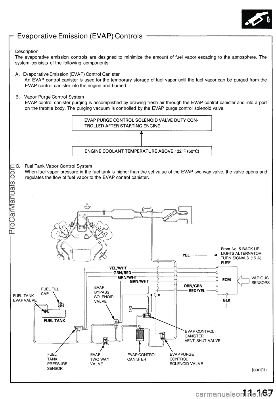
Evaporative Emission (EVAP) Controls
Description
The evaporative emission controls are designed to minimize the amount of fuel vapor escaping to the atmosphere. The
system consists of the following components:
A. Evaporative Emission (EVAP) Control Canister
An EVAP control canister is used for the temporary storage of fuel vapor until the fuel vapor can be purged from the
EVAP control canister into the engine and burned.
B. Vapor Purge Control System
EVAP control canister purging is accomplished by drawing fresh air through the EVAP control canister and into a port
on the throttle body. The purging vacuum is controlled by the EVAP purge control solenoid valve.
C. Fuel Tank Vapor Control System
When fuel vapor pressure in the fuel tank is higher than the set value of the EVAP two way valve, the valve opens and
regulates the flow of fuel vapor to the EVAP control canister.
From No. 5 BACK-UP
LIGHTS ALTERNATOR
TURN SIGNALS (15 A)
FUSE
FUEL TANK
EVAP VALVE
EVAP
BYPASS
SOLENOID
VALVE
VARIOUS
SENSORS
EVAP CONTROL
CANISTER
VENT SHUT VALVE
FUEL
TANK
PRESSURE
SENSOR
EVAP
TWO WAY
VALVE
EVAP CONTROL
CANISTER
EVAP PURGE
CONTROL
SOLENOID VALVE
(cont'd)
FUEL FILL
CAPProCarManuals.com
Page 1016 of 1503

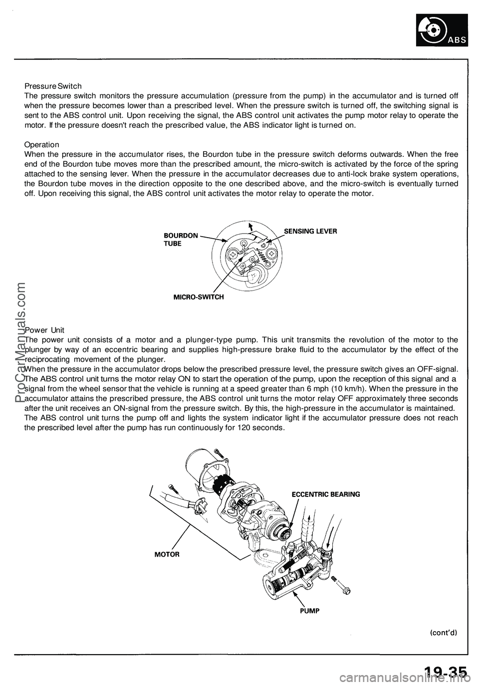
Pressure Switch
The pressure switch monitors the pressure accumulation (pressure from the pump) in the accumulator and is turned off
when the pressure becomes lower than a prescribed level. When the pressure switch is turned off, the switching signal is
sent to the ABS control unit. Upon receiving the signal, the ABS control unit activates the pump motor relay to operate the
motor. If the pressure doesn't reach the prescribed value, the ABS indicator light is turned on.
Operation
When the pressure in the accumulator rises, the Bourdon tube in the pressure switch deforms outwards. When the free
end of the Bourdon tube moves more than the prescribed amount, the micro-switch is activated by the force of the spring
attached to the sensing lever. When the pressure in the accumulator decreases due to anti-lock brake system operations,
the Bourdon tube moves in the direction opposite to the one described above, and the micro-switch is eventually turned
off. Upon receiving this signal, the ABS control unit activates the motor relay to operate the motor.
Power Unit
The power unit consists of a motor and a plunger-type pump. This unit transmits the revolution of the motor to the
plunger by way of an eccentric bearing and supplies high-pressure brake fluid to the accumulator by the effect of the
reciprocating movement of the plunger.
When the pressure in the accumulator drops below the prescribed pressure level, the pressure switch gives an OFF-signal.
The ABS control unit turns the motor relay ON to start the operation of the pump, upon the reception of this signal and a
signal from the wheel sensor that the vehicle is running at a speed greater than 6 mph (10 km/h). When the pressure in the
accumulator attains the prescribed pressure, the ABS control unit turns the motor relay OFF approximately three seconds
after the unit receives an ON-signal from the pressure switch. By this, the high-pressure in the accumulator is maintained.
The ABS control unit turns the pump off and lights the system indicator light if the accumulator pressure does not reach
the prescribed level after the pump has run continuously for 120 seconds.ProCarManuals.com
Page 1117 of 1503
Front Bumper
Replacement
1. Loosen the mounting screw, then pull the right and left front turn signal lights out and disconnect the connectors.
2. Remove the skirt covers, then remove the bumper mounting bolts on each side, and lower skirt mounting bolt.
3. Lower the inner fender, then remove the bumper mounting nuts and the skirt mounting bolts from inside the front
fender on each side.
4. Lift and remove the front bumper.
NOTE:
• Disconnect the washer hose, horn connecters, and ambient sensor connector.
• An assistant is helpful when removing the front bumper.
• Take care not to scratch the front bumper.
5. Installation is the reverse of the removal procedure.
NOTE: Insert the bumper bracket hooks into the bumper bracket holes.ProCarManuals.com
Page 1236 of 1503
Dashboard, Doo r an d Floo r
DRIVER' S DOO R PANE LABS CONTRO L UNI T
DAYTIM E RUNNIN GLIGHTS CONTRO LUNIT (Canada )
POWER WINDO WCONTRO L UNI T
SECURIT Y CONTRO L UNI T
POWE
R DOO R LOC K
CONTRO L UNI T
CIGARETT E LIGHTE RRELAYWire colors : YEL/RED ,
BLU/GRN , BRN/YEL . an d BL K FOO
T WEL L BAS S SPEAKE R
EPS CONTRO L UNI T(Behin d foo t wel lbass speaker )
RIGH T FRON T FLOO R
PANEL
SRS UNI T
STARTE R CU T RELA Y
Wir e colors : BLK/WHT ,
BLK/WHT , BLK/GRN ,
an d BLK/BL U
ProCarManuals.com
Page 1237 of 1503
Relay and Control Unit Locations
Rear Bulkhead
PGM-FI MAIN RELAY
THROTTLE VALVE CONTROL
MOTOR RELAY
Wire colors: BLK,
YEL/BLK, GRN/RED,
and WHT/BLU
DASH LIGHTS
BRIGHTNESS
CONTROL UNIT
TRANSMISSION CONTROL
MODULE (TCM) (A/T)
PULSE UNIT (M/T)
ABS INDICATOR LIGHT
RELAY
Wire colors: BLU/WHT,
BLK, YEL/BLK, BLU/WHT
TCS CONTROL UNIT
FAN CONTROL
UNIT
ECMProCarManuals.com
Page 1292 of 1503
Gauge Assembly
Bulb Locations
GAUGE LIGHTS (1.4 Wx 2)
SRS INDICATOR LIGHT (1.4 W)
RIGHT TURN SIGNAL INDICATOR LIGHT 11.4 W)
EPS INDICATOR LIGHT (1.4 W)
BRAKE SYSTEM LIGHT (1.4 W)
SEAT BELT REMINDER LIGHT (1.4 W)
IMMOBILIZER INDICATOR
LIGHT (1.4 W)
LOW FUEL INDICATOR
LIGHT (1.4 W)
GAUGE LIGHT
(1.4
W)
TCS INDICATOR LIGHT (1.96 W)
LEFT TURN SIGNAL INDICATOR LIGHT (1.4 W)
ABS
INDICATOR LIGHT (1.4 W)
CHARGING SYSTEM LIGHT (1.4 W)
MALFUNCTION
INDICATOR
LAMP (MIL)
(1.4
W)
CRUISE INDICATOR LIGHT
(1.96
W)
LOW OIL PRESSURE
INDICATOR
LIGHT (1.4 W)
GAUGE LIGHT
.4W)
GAUGE LIGHT
(3.0
W)
GAUGE LIGHT
GAUGE LIGHT HIGH BEAM INDICATOR (3.0 W)
(3.0 W) LIGHT (1.4 W)ProCarManuals.com