1997 ACURA NSX lights
[x] Cancel search: lightsPage 1322 of 1503
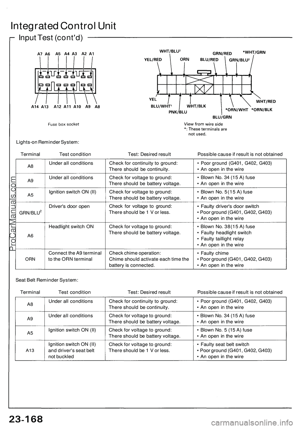
Integrated Control Unit
Input Test (cont'd)
Lights-on Reminder System:
Terminal
Test condition
Test: Desired result
Possible cause if result is not obtained
A8
A9
A5
GRN/BLU2
A6
ORN
Under all conditions
Under all conditions
Ignition switch ON (II)
Driver's door open
Headlight switch ON
Connect the A9 terminal
to the ORN terminal
Check for continuity to ground:
There should be continuity.
Check for voltage to ground:
There should be battery voltage.
Check for voltage to ground:
There should be battery voltage.
Check for voltage to ground:
There should be 1 V or less.
Check for voltage to ground:
There should be battery voltage.
Check chime operation:
Chime should activate each time the
battery is connected.
• Poor ground (G401, G402, G403)
• An open in the wire
• Blown No. 34 (15 A) fuse
• An open in the wire
• Blown No. 5(15 A) fuse
• An open in the wire
• Faulty driver's door switch
• Poor ground (G401, G402, G403)
• An open in the wire
• Blown No. 38(15 A) fuse
• Faulty headlight switch
• Faulty taillight relay
• An open in the wire
• Faulty chime
• Poor ground (G401, G402, G403)
• An open in the wire
Seat Belt Reminder System:
Terminal Test condition
Test: Desired result
Possible cause if result is not obtained
A8
A9
A5
A13
Under all conditions
Under all conditions
Ignition switch ON (II)
Ignition switch ON (II)
and driver's seat belt
not buckled
Check for continuity to ground:
There should be continuity.
Check for voltage to ground:
There should be battery voltage.
Check for voltage to ground:
There should be battery voltage.
Check for voltage to ground:
There should be 1 V or less.
• Poor ground (G401, G402, G403)
• An open in the wire
• Blown No. 34 (15 A) fuse
• An open in the wire
• Blown No. 5 (15 A) fuse
• An open in the wire
• Faulty seat belt switch
• Poor ground (G401, G402, G403)
• An open in the wireProCarManuals.com
Page 1324 of 1503
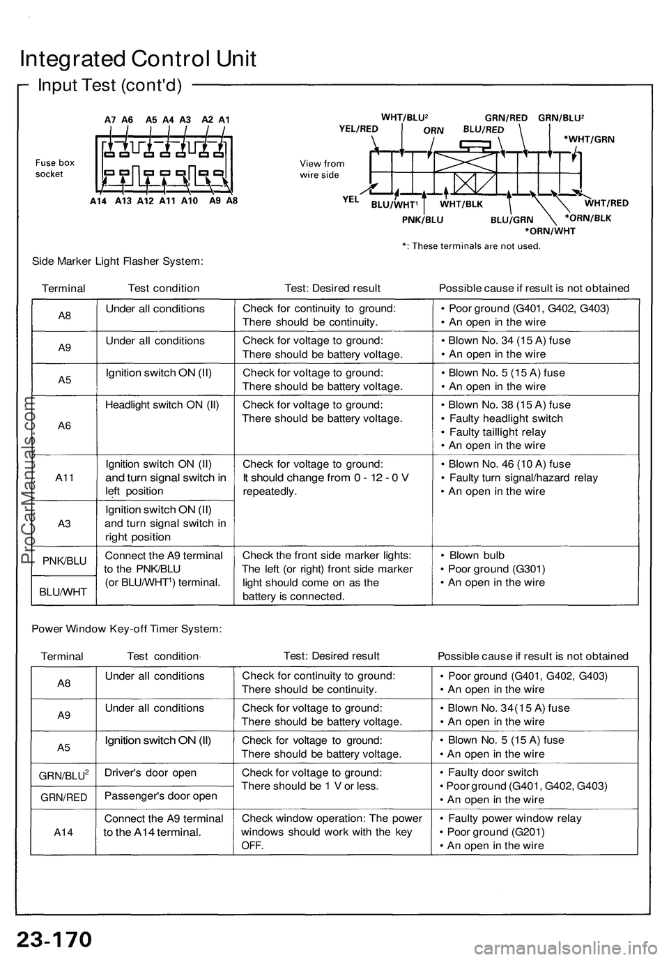
Integrated Contro l Uni t
Inpu t Tes t (cont'd )
Side Marke r Ligh t Flashe r System :
Termina l Tes
t conditio n Test: Desire d resul t Possible caus e if resul t i s no t obtaine d
A8
A9
A 5
A 6
A1 1
A3
PNK/BL U
BLU/WH T
Under al l condition s
Under al l condition s
Ignition switc h O N (II )
Headligh t switc h O N (II )
Ignitio n switc h O N (II )
and tur n signa l switc h in
lef t positio n
Ignition switc h O N (II )
an d tur n signa l switc h i n
righ t positio n
Connec t th e A 9 termina l
t o th e PNK/BL U
(o r BLU/WHT
1) terminal .Chec
k fo r continuit y t o ground :
Ther e shoul d b e continuity .
Chec k fo r voltag e t o ground :
Ther e shoul d b e batter y voltage .
Chec k fo r voltag e to ground :
Ther e shoul d b e batter y voltage .
Chec k fo r voltag e t o ground :
Ther e shoul d b e batter y voltage .
Chec k fo r voltag e t o ground :
It shoul d chang e fro m 0 - 1 2 - 0 V
repeatedly .
Chec k th e fron t sid e marke r lights :
Th e lef t (o r right ) fron t sid e marke r
ligh t shoul d com e o n a s th e
batter y is connected . •
Poo r groun d (G401 , G402 , G403 )
• A n ope n in th e wir e
• Blow n No . 3 4 (1 5 A ) fus e
• A n ope n in th e wir e
• Blow n No . 5 (1 5 A ) fus e
• A n ope n in th e wir e
• Blow n No . 3 8 (1 5 A ) fus e
• Fault y headligh t switc h
• Fault y tailligh t rela y
• A n ope n in th e wir e
• Blow n No . 4 6 (1 0 A ) fus e
• Fault y tur n signal/hazar d rela y
• A n ope n i n th e wir e
• Blow n bul b
• Poo r groun d (G301 )
• A n ope n in th e wir e
Powe r Windo w Key-of f Time r System :
Termina l Tes
t conditio n Test
: Desire d resul t
Possible caus e if resul t i s no t obtaine d
A8
A 9
A 5
GRN/BLU2
GRN/RE D
A14
Unde r al l condition s
Unde r al l condition s
Ignition switc h O N (II )
Driver' s doo r ope n
Passenger' s doo r ope n
Connec t th e A 9 termina l
to th e A1 4 terminal .
Check fo r continuit y t o ground :
Ther e shoul d b e continuity .
Chec k fo r voltag e t o ground :
Ther e shoul d b e batter y voltage .
Chec k fo r voltag e t o ground :
Ther e shoul d b e batter y voltage .
Chec k fo r voltag e t o ground :
Ther e shoul d b e 1 V or less .
Chec k windo w operation : Th e powe r
window s shoul d wor k wit h th e ke y
OFF .
• Poo r groun d (G401 , G402 , G403 )
• A n ope n i n th e wir e
• Blow n No . 34(1 5 A ) fus e
• A n ope n i n th e wir e
• Blow n No . 5 (1 5 A ) fus e
• A n ope n in th e wir e
• Fault y doo r switc h
• Poo r groun d (G401 , G402 , G403 )
• A n ope n in th e wir e
• Fault y powe r windo w rela y
• Poo r groun d (G201 )
• A n ope n in th e wir e
ProCarManuals.com
Page 1326 of 1503
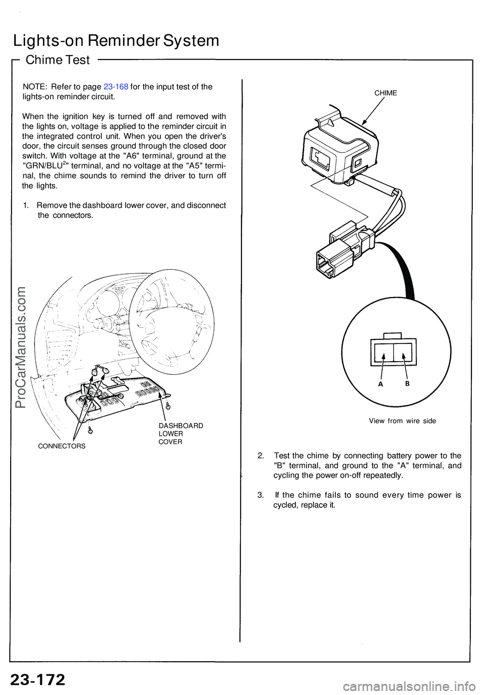
Lights-on Reminde r Syste m
Chime Tes t
NOTE : Refe r t o pag e 23-168 for the input test of the
lights-on reminde r circuit.
Whe n th e ignitio n ke y i s turne d of f an d remove d wit h
th e light s on , voltag e is applie d t o th e reminde r circui t i n
th e integrate d contro l unit . Whe n yo u ope n th e driver' s
door , th e circui t sense s groun d throug h th e close d doo r
switch . Wit h voltag e a t th e "A6 " terminal , groun d a t th e
"GRN/BLU
2" terminal , an d n o voltag e a t th e "A5 " termi -
nal , th e chim e sound s t o remin d th e drive r t o tur n of f
th e lights .
1 . Remov e th e dashboar d lowe r cover , an d disconnec t
th e connectors .
CONNECTOR S
DASHBOARDLOWERCOVER
CHIME
Vie w fro m wir e sid e
2. Tes t th e chim e b y connectin g batter y powe r t o th e
"B " terminal , an d groun d t o th e "A " terminal , an d
cyclin g th e powe r on-of f repeatedly .
3 . I f th e chim e fail s t o soun d ever y tim e powe r i s
cycled , replac e it .
ProCarManuals.com
Page 1331 of 1503
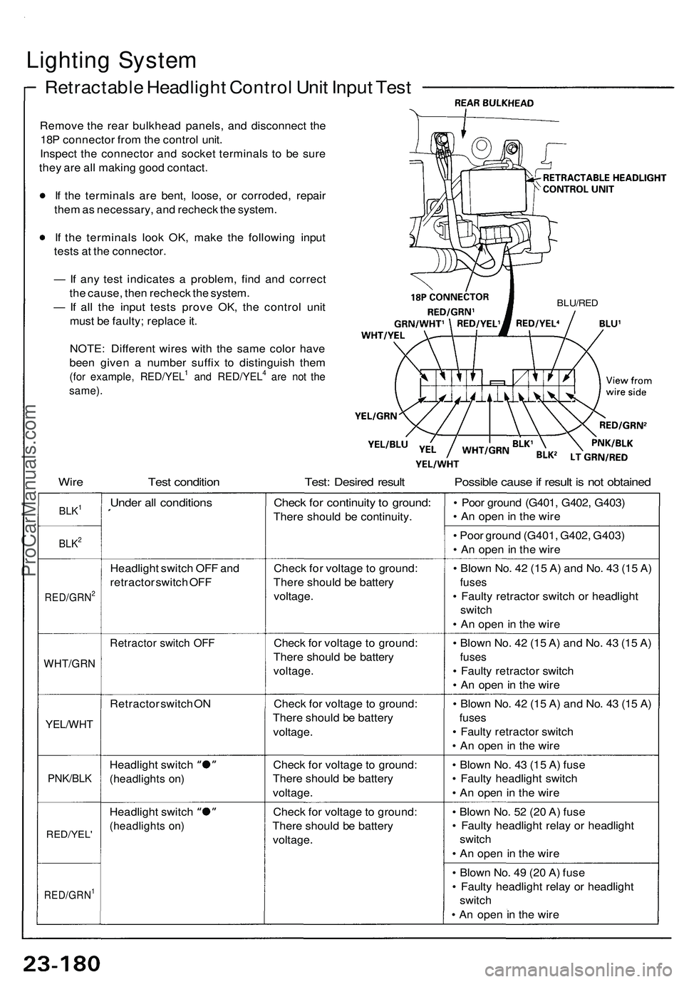
Lighting System
Retractable Headlight Control Unit Input Test
Remove the rear bulkhead panels, and disconnect the
18P connector from the control unit.
Inspect the connector and socket terminals to be sure
they are all making good contact.
If the terminals are bent, loose, or corroded, repair
them as necessary, and recheck the system.
If the terminals look OK, make the following input
tests at the connector.
— If any test indicates a problem, find and correct
the cause, then recheck the system.
— If all the input tests prove OK, the control unit
must be faulty; replace it.
BLU/RED
Wire Test condition Test: Desired result Possible cause if result is not obtained
BLK1
BLK2
RED/GRN2
WHT/GRN
YEL/WHT
PNK/BLK
RED/YEL'
RED/GRN1
Under all conditions
Headlight switch OFF and
retractor switch OFF
Retractor switch OFF
Retractor switch ON
Headlight switch
(headlights on)
Headlight switch
(headlights on)
Check for continuity to ground:
There should be continuity.
Check for voltage to ground:
There should be battery
voltage.
Check for voltage to ground:
There should be battery
voltage.
Check for voltage to ground:
There should be battery
voltage.
Check for voltage to ground:
There should be battery
voltage.
Check for voltage to ground:
There should be battery
voltage.
• Poor ground (G401, G402, G403)
• An open in the wire
• Poor ground (G401, G402, G403)
• An open in the wire
• Blown No. 42 (15 A) and No. 43 (15 A)
fuses
• Faulty retractor switch or headlight
switch
• An open in the wire
• Blown No. 42 (15 A) and No. 43 (15 A)
fuses
• Faulty retractor switch
• An open in the wire
• Blown No. 42 (15 A) and No. 43 (15 A)
fuses
• Faulty retractor switch
• An open in the wire
• Blown No. 43 (15 A) fuse
• Faulty headlight switch
• An open in the wire
• Blown No. 52 (20 A) fuse
• Faulty headlight relay or headlight
switch
• An open in the wire
• Blown No. 49 (20 A) fuse
• Faulty headlight relay or headlight
switch
• An open in the wire
NOTE: Different wires with the same color have
been given a number suffix to distinguish them
(for example, RED/YEL1 and RED/YEL4 are not the
same).ProCarManuals.com
Page 1332 of 1503
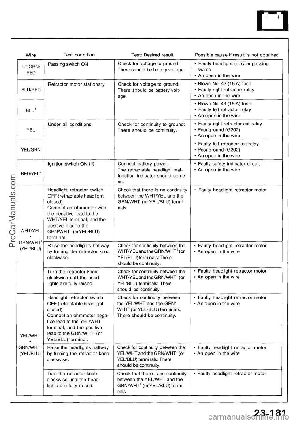
Wire
Test condition
Test: Desired result
Possible cause if result is not obtained
LT
GRN/
RED
Passing switch ON
Check for voltage to ground:
There should be battery voltage.
• Faulty headlight relay or passing
switch
• An open in the wire
BLU/RED
Retractor motor stationary
Check for voltage to ground:
There should be battery volt-
age.
• Blown No. 42 (15 A) fuse
• Faulty right retractor relay
• An open in the wire
BLU1
• Blown No. 43 (15 A) fuse
• Faulty left retractor relay
• An open in the wire
Under all conditions
YEL
Check for continuity to ground:
There should be continuity.
• Faulty right retractor cut relay
• Poor ground (G202)
• An open in the wire
YEL/GRN
• Faulty left retractor cut relay
• Poor ground (G202)
• An open in the wire
Ignition switch ON
RED/YEL4
Connect battery power:
The retractable headlight mal-
function indicator should come
on.
• Faulty safety indicator circuit
• An open in the wire
Headlight retractor switch
OFF (retractable headlight
closed)
Connect an ohmmeter with
the negative lead to the
WHT/YEL terminal, and the
positive lead to the
GRN/WHT (orYEL/BLU)
terminal.
Check that there is no continuity
between the WHT/YEL and the
GRN/WHT (or YEL/BLU) termi-
nals.
• Faulty headlight retractor motor
Raise the headlights halfway
by turning the retractor knob
clockwise.
Check for continuity between the
WHT/YEL and the GRN/WHT1 (or
YEL/BLU) terminals: There
should be continuity.
• Faulty headlight retractor motor
• An open in the wire
Turn the retractor knob
clockwise until the head-
lights are fully raised.
Check for continuity between the
WHT/YEL and the GRN/WHT1 (or
YEL/BLU) terminals: There
should be continuity.
• Faulty headlight retractor motor
• An open in the wire
Headlight retractor switch
OFF (retractable headlight
closed)
Connect an ohmmeter nega-
tive lead to the YEL/WHT
terminal, and the positive
lead to the GRN/WHT' (or
YEL/BLU) terminal.
Check for continuity between
the YEL/WHT and the GRN/
WHT1 (or YEL/BLU) terminals:
There should be continuity.
• Faulty headlight retractor motor
• An open in the wire
Raise the headlights halfway
by turning the retractor knob
clockwise.
Check for continuity between the
YEL/WHT and the GRN/WHT1 (or
YEL/BLU) terminals: There
should be continuity.
• Faulty headlight retractor motor
• An open in the wire
Turn the retractor knob
clockwise until the head-
lights are fully raised.
Check that there is no continuity
between the YEL/WHT and the
GRN/WHT1 (or YEL/BLU) termi-
nals.
• Faulty headlight retractor motor
GRN/WHT1
(YEL/BLU)
WHT/YEL
GRN/WHT1
(YEL/BLU)
YEL/WHTProCarManuals.com
Page 1339 of 1503
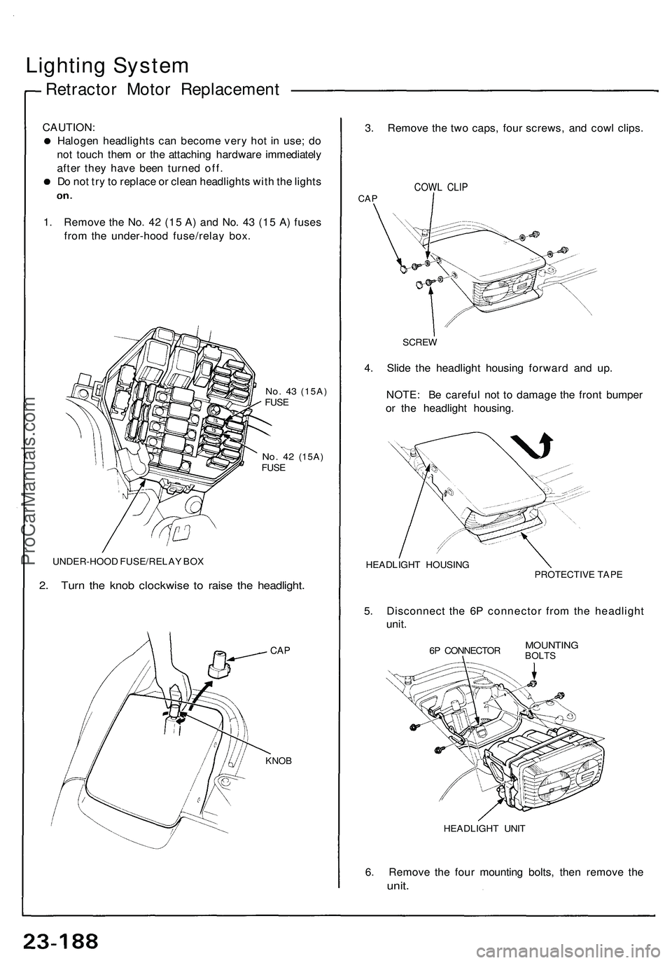
Lighting System
Retractor Motor Replacement
CAUTION:
Halogen headlights can become very hot in use; do
not touch them or the attaching hardware immediately
after they have been turned off.
Do not try to replace or clean headlights with the lights
1. Remove the No. 42 (15 A) and No. 43 (15 A) fuses
from the under-hood fuse/relay box.
No. 43
(15A)
FUSE
No. 42
(15A)
FUSE
UNDER-HOOD FUSE/RELAY BOX
2. Turn the knob clockwise to raise the headlight.
CAP
3. Remove the two caps, four screws, and cowl clips.
COWL CLIP
CAP
4. Slide the headlight housing forward and up.
NOTE: Be careful not to damage the front bumper
or the headlight housing.
HEADLIGHT HOUSING
PROTECTIVE TAPE
5. Disconnect the 6P connector from the headlight
unit.
6P CONNECTOR
MOUNTING
BOLTS
HEADLIGHT UNIT
6. Remove the four mounting bolts, then remove the
unit.
KNOB
SCREWProCarManuals.com
Page 1346 of 1503
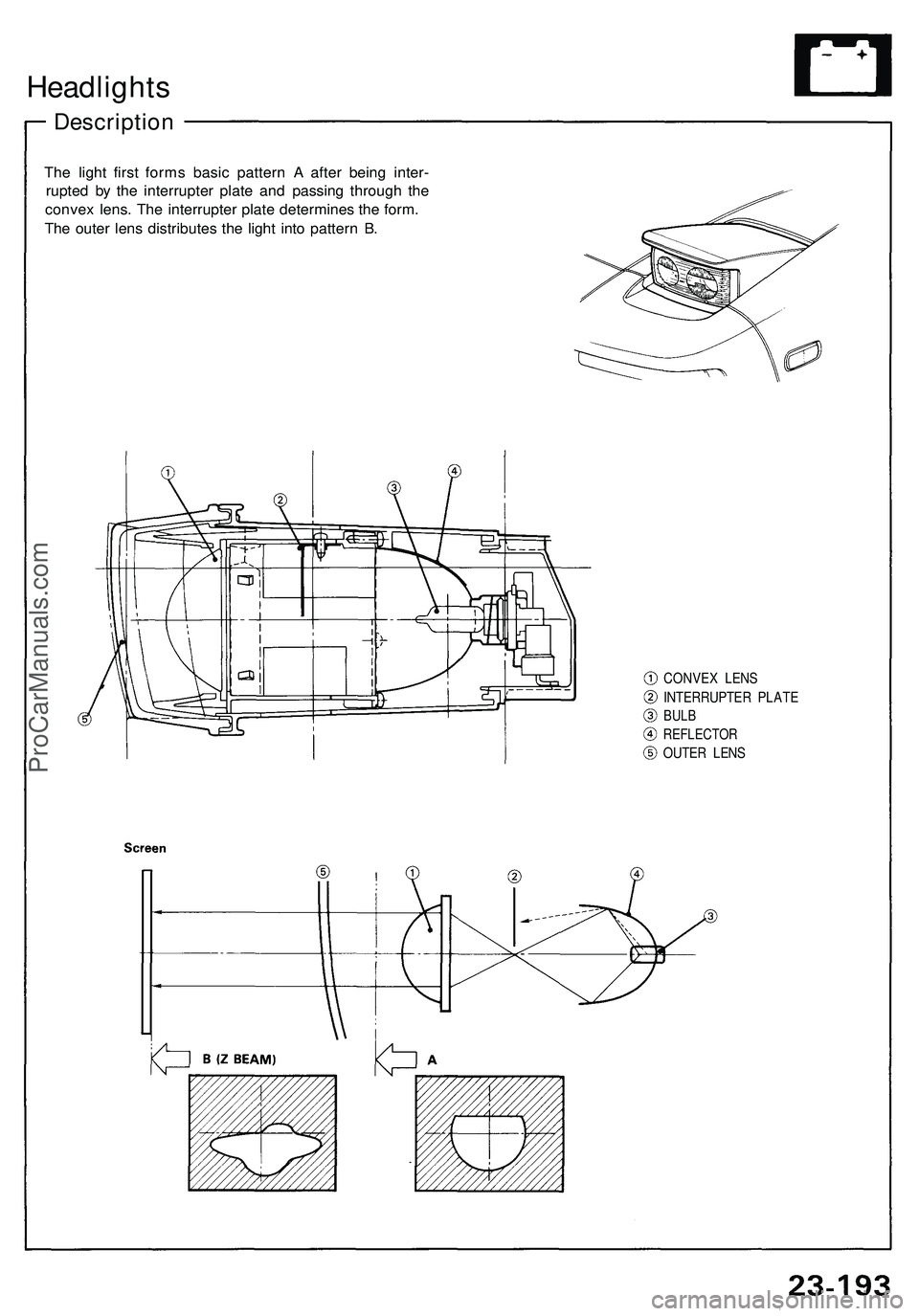
Headlights
Description
The light first forms basic pattern A after being inter-
rupted by the interrupter plate and passing through the
convex lens. The interrupter plate determines the form.
The outer lens distributes the light into pattern B.
CONVEX LENS
INTERRUPTER PLATE
BULB
REFLECTOR
OUTER LENSProCarManuals.com
Page 1347 of 1503
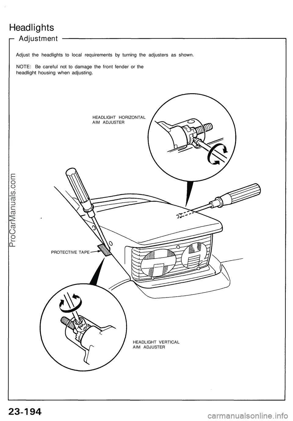
Headlights
Adjustment
Adjust the headlights to local requirements by turning the adjusters as shown.
NOTE: Be careful not to damage the front fender or the
headlight housing when adjusting.
HEADLIGHT HORIZONTAL
AIM ADJUSTER
HEADLIGHT VERTICAL
AIM ADJUSTER
PROTECTIVE TAPEProCarManuals.com