1997 ACURA NSX sensor
[x] Cancel search: sensorPage 1295 of 1503
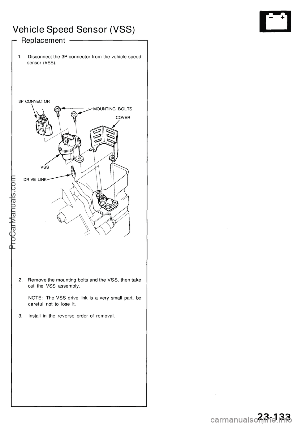
Vehicle Speed Sensor (VSS)
Replacement
1. Disconnect the 3P connector from the vehicle speed
sensor (VSS).
3P CONNECTOR
MOUNTING BOLTS
2. Remove the mounting bolts and the VSS, then take
out the VSS assembly.
NOTE: The VSS drive link is a very small part, be
careful not to lose it.
3. Install in the reverse order of removal.
VSS
DRIVE LINK
COVERProCarManuals.com
Page 1308 of 1503
Safety Indicato r
Componen t Locatio n Inde x
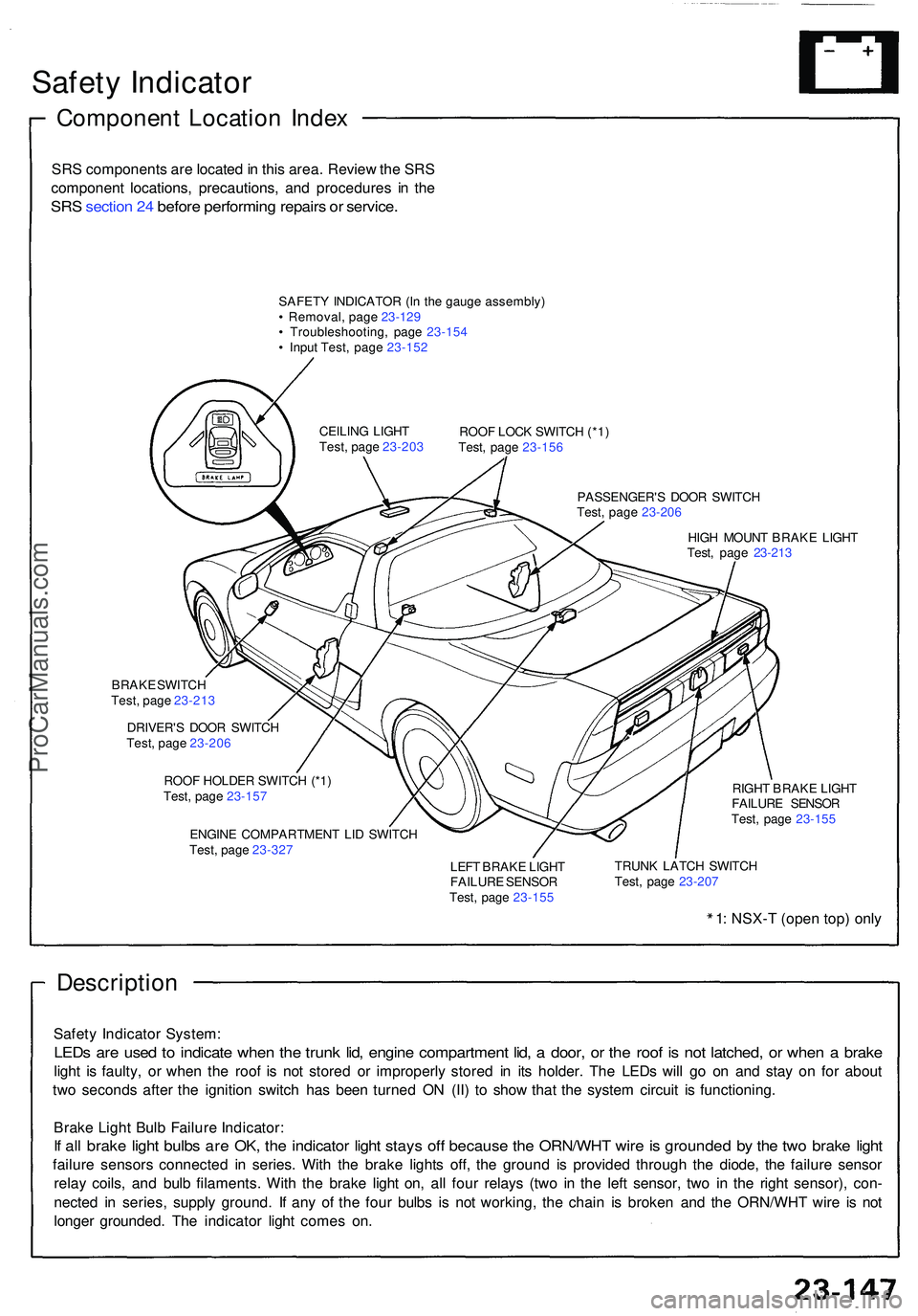
SRS component s ar e locate d in thi s area . Revie w th e SR S
componen t locations , precautions , an d procedure s i n th e
SR S sectio n 24 befor e performin g repair s o r service .
SAFET Y INDICATO R (I n th e gaug e assembly )
• Removal , pag e 23-12 9
• Troubleshooting , pag e 23-15 4
• Inpu t Test , pag e 23-15 2
ROOF LOC K SWITC H (*1 )
Test , pag e 23-15 6
PASSENGER' S DOO R SWITC H
Test , pag e 23-20 6
HIG H MOUN T BRAK E LIGH T
Test , pag e 23-21 3
CEILIN
G LIGH T
Test , pag e 23-20 3
BRAK E SWITC H
Test , pag e 23-21 3
DRIVER' S DOO R SWITC H
Test , pag e 23-20 6
ROO F HOLDE R SWITC H (*1 )
Test , pag e 23-15 7
ENGIN E COMPARTMEN T LI D SWITC H
Test , pag e 23-32 7 RIGH
T BRAK E LIGH T
FAILUR E SENSO R
Test , pag e 23-15 5
LEF T BRAK E LIGH T
FAILUR E SENSO R
Test , pag e 23-15 5 TRUN
K LATC H SWITC H
Test , pag e 23-20 7
1: NSX- T (ope n top ) onl y
Descriptio n
Safety Indicato r System :
LEDs ar e use d t o indicat e whe n th e trun k lid , engin e compartmen t lid , a door , o r th e roo f i s no t latched , o r whe n a brak e
light i s faulty , o r whe n th e roo f i s no t store d o r improperl y store d i n it s holder . Th e LED s wil l g o o n an d sta y o n fo r abou t
tw o second s afte r th e ignitio n switc h ha s bee n turne d O N (II ) t o sho w tha t th e syste m circui t i s functioning .
Brak e Ligh t Bul b Failur e Indicator :
If al l brak e ligh t bulb s ar e OK , th e indicato r ligh t stay s of f becaus e th e ORN/WH T wir e is grounde d b y th e tw o brak e ligh t
failur e sensor s connecte d i n series . Wit h th e brak e light s off , th e groun d i s provide d throug h th e diode , th e failur e senso r
rela y coils , an d bul b filaments . Wit h th e brak e ligh t on , al l fou r relay s (tw o i n th e lef t sensor , tw o i n th e righ t sensor) , con -
necte d i n series , suppl y ground . I f an y o f th e fou r bulb s i s no t working , th e chai n i s broke n an d th e ORN/WH T wir e i s no t
longe r grounded . Th e indicato r ligh t come s on .
ProCarManuals.com
Page 1310 of 1503
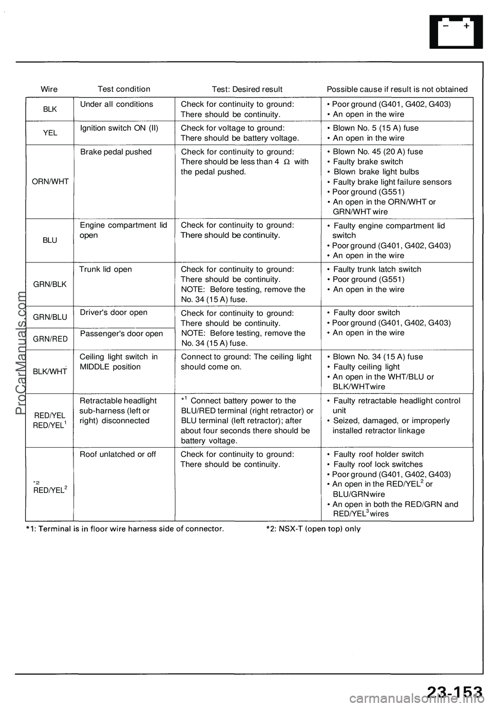
Wire Tes
t conditio n
Test: Desire d resul t Possible caus e if resul t i s no t obtaine d
BLKUnde r al l condition sCheck fo r continuit y t o ground :
Ther e shoul d b e continuity . •
Poo r groun d (G401 , G402 , G403 )
• A n ope n in th e wir e
YELIgnitio n switc h O N (II ) Check fo r voltag e t o ground :
Ther e shoul d b e batter y voltage . •
Blow n No . 5 (1 5 A ) fus e
• A n ope n i n th e wir e
Brak e peda l pushe d Check fo r continuit y t o ground :
Ther e shoul d b e les s tha n 4 W wit h
th e peda l pushed .
ORN/WH T
• Blow n No . 4 5 (2 0 A ) fus e
• Fault y brak e switc h
• Blow n brak e ligh t bulb s
• Fault y brak e ligh t failur e sensor s
• Poo r groun d (G551 )
• A n ope n in th e ORN/WH T o r
GRN/WH T wir e
BLU
Engin e compartmen t li d
ope n
Chec k fo r continuit y t o ground :
There shoul d b e continuity .
• Fault y engin e compartmen t li d
switc h
• Poo r groun d (G401 , G402 , G403 )
• A n ope n i n th e wir e
Trun k li d ope n
GRN/BL K
Check fo r continuit y t o ground :
Ther e shoul d b e continuity .
NOTE : Befor e testing , remov e th e
No . 3 4 (1 5 A ) fuse . •
Fault y trun k latc h switc h
• Poo r groun d (G551 )
• A n ope n in th e wir e
GRN/BL UDriver's doo r ope n
GRN/RE DPassenger' s doo r ope n Chec
k fo r continuit y t o ground :
Ther e shoul d b e continuity .
NOTE : Befor e testing , remov e th e
No . 3 4 (1 5 A ) fuse . •
Fault y doo r switc h
• Poo r groun d (G401 , G402 , G403 )
• A n ope n i n th e wir e
BLK/WH T
Ceiling ligh t switc h i n
MIDDL E positio n Connec
t t o ground : Th e ceilin g ligh t
shoul d com e on . •
Blow n No . 3 4 (1 5 A ) fus e
• Fault y ceilin g ligh t
• A n ope n in th e WHT/BL U o r
BLK/WHTwir e
RED/YEL
RED/YEL1
Retractabl e headligh t
sub-harnes s (lef t o r
right ) disconnecte d*1 Connec
t batter y powe r t o th e
BLU/RE D termina l (righ t retractor ) o r
BL U termina l (lef t retractor) ; afte r
abou t fou r second s ther e shoul d b e
batter y voltage . •
Fault y retractabl e headligh t contro l
unit
• Seized , damaged , o r improperl y
installe d retracto r linkag e
Roo f unlatche d o r of f Check fo r continuit y t o ground :
Ther e shoul d b e continuity .
*2RED/YEL2
• Fault y roo f holde r switc h
• Fault y roo f loc k switche s
• Poo r groun d (G401 , G402 , G403 )
• A n ope n in th e RED/YEL
2 o r
BLU/GR N wir e
• A n ope n in bot h th e RED/GR N an d
RED/YEL3 wire s
ProCarManuals.com
Page 1312 of 1503
Brake Ligh t Failur e Senso r Tes t
1. Firs t mak e sur e th e brak e light s com e o n whe n th e
brak e peda l i s pressed .
I f al l th e brak e light s com e on , g o t o ste p 2 .
I f on e o f th e brak e light s doe s no t com e on , chec k
whethe r th e bul b i s blown . I f th e bul b i s OK , g o
t o ste p 2 .
I f non e o f th e brak e light s com e on , chec k th e
brak e ligh t circui t.
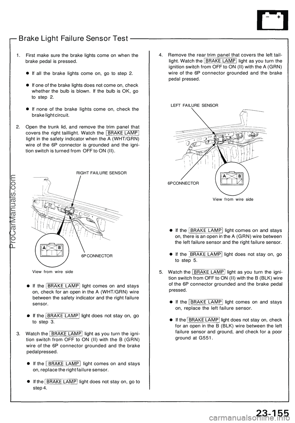
2 . Ope n th e trun k lid , an d remov e th e tri m pane l tha t
cover s th e righ t taillight . Watc h th e
ligh t i n th e safet y indicato r whe n th e A (WHT/GRN )
wir e o f th e 6 P connecto r i s grounde d an d th e igni -
tio n switc h is turne d fro m OF F to O N (II) .
RIGH T FAILUR E SENSO R
6 P CONNECTO R
Vie w fro m wir e sid e LEF
T FAILUR E SENSO R
6 P CONNECTO R
View fro m wir e sid e
If th e ligh t come s o n an d stay s
on, ther e is a n ope n in th e A (GRN ) wir e betwee n
th e lef t failur e senso r an d th e righ t failur e sensor .
If th e ligh t doe s no t sta y on , g o
t o ste p 5 .
5. Watc h th e ligh t a s yo u tur n th e igni -
tio n switc h fro m OF F to O N (II ) wit h th e B (BLK ) wir e
o f th e 6 P connecto r grounde d an d th e brak e peda l
pressed .
If th e ligh t come s o n an d stay s
on , replac e th e lef t failur e sensor .
If th e ligh t doe s no t sta y on , chec k
fo r a n ope n in th e B (BLK ) wir e betwee n th e lef t
failur e senso r an d ground , an d chec k fo r a poo r
groun d a t G551 .
If th e ligh t come s o n an d stay s
on , chec k fo r a n ope n in th e A (WHT/GRN ) wir e
betwee n th e safet y indicato r an d th e righ t failur e
sensor .
If th e ligh t doe s no t sta y on , g o
to ste p 3 .
3. Watc h th e ligh t a s yo u tur n th e igni -
tio n switc h fro m OF F t o O N (II ) wit h th e B (GRN )
wir e o f th e 6 P connecto r grounde d an d th e brak e
peda l pressed .
If th e ligh t come s o n an d stay s
on , replac e th e righ t failur e sensor .
If th e ligh t doe s no t sta y on , g o t o
ste p 4 . 4
. Remov e th e rea r tri m pane l tha t cover s th e lef t tail -
light . Watc h th e ligh t a s yo u tur n th e
ignitio n switc h fro m OF F to O N (II ) wit h th e A (GRN )
wir e o f th e 6 P connecto r grounde d an d th e brak e
pedal pressed .
ProCarManuals.com
Page 1363 of 1503
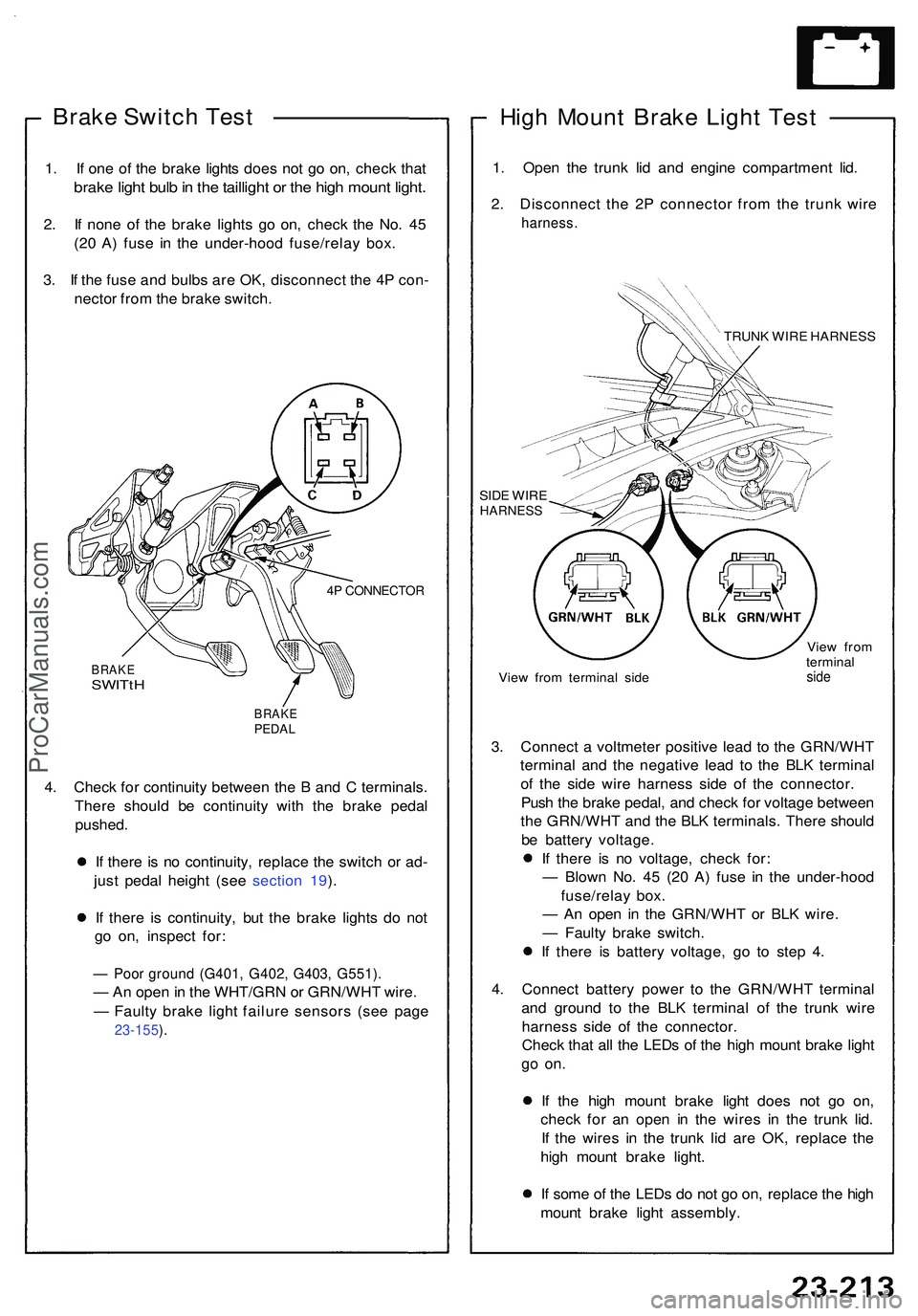
Brake Switc h Tes t
1. I f on e o f th e brak e light s doe s no t g o on , chec k tha t
brak e ligh t bul b in th e tailligh t o r th e hig h moun t light .
2. I f non e o f th e brak e light s g o on , chec k th e No . 4 5
(2 0 A ) fus e i n th e under-hoo d fuse/rela y box .
3 . I f th e fus e an d bulb s ar e OK , disconnec t th e 4 P con -
necto r fro m th e brak e switch .
4P CONNECTO R
BRAKESWITtH
BRAK EPEDAL
4. Chec k fo r continuit y betwee n th e B an d C terminals .
Ther e shoul d b e continuit y wit h th e brak e peda l
pushed .
I f ther e i s n o continuity , replac e th e switc h o r ad -
jus t peda l heigh t (se e sectio n 19 ).
I f ther e i s continuity , bu t th e brak e light s d o no t
g o on , inspec t for :
— Poo r groun d (G401 , G402 , G403 , G551) .
— An ope n in th e WHT/GR N o r GRN/WH T wire .
— Fault y brak e ligh t failur e sensor s (se e pag e
23-155 ).
Hig h Moun t Brak e Ligh t Tes t
1. Ope n th e trun k li d an d engin e compartmen t lid .
2 . Disconnec t th e 2 P connecto r fro m th e trun k wir e
harness .
TRUNK WIR E HARNES S
SID E WIR E
HARNES S
View fro m termina l sid e Vie
w fro m
termina lside
3. Connec t a voltmete r positiv e lea d t o th e GRN/WH T
termina l an d th e negativ e lea d t o th e BL K termina l
o f th e sid e wir e harnes s sid e o f th e connector .
Pus h th e brak e pedal , an d chec k fo r voltag e betwee n
th e GRN/WH T an d th e BL K terminals . Ther e shoul d
b e batter y voltage .
I f ther e i s n o voltage , chec k for :
— Blow n No . 4 5 (2 0 A ) fus e i n th e under-hoo d
fuse/rela y box .
— A n ope n i n th e GRN/WH T o r BL K wire .
— Fault y brak e switch .
I f ther e i s batter y voltage , g o t o ste p 4 .
4 . Connec t batter y powe r t o th e GRN/WH T termina l
an d groun d t o th e BL K termina l o f th e trun k wir e
harnes s sid e o f th e connector .
Chec k tha t al l th e LED s o f th e hig h moun t brak e ligh t
go on .
If th e hig h moun t brak e ligh t doe s no t g o on ,
chec k fo r a n ope n i n th e wire s i n th e trun k lid .
I f th e wire s i n th e trun k li d ar e OK , replac e th e
hig h moun t brak e light .
I f som e o f th e LED s d o no t g o on , replac e th e hig h
moun t brak e ligh t assembly .
ProCarManuals.com
Page 1366 of 1503
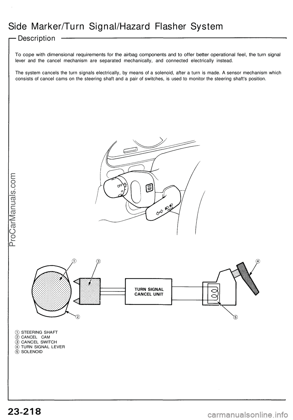
Side Marker/Turn Signal/Hazard Flasher System
Description
To cope with dimensional requirements for the airbag components and to offer better operational feel, the turn signal
lever and the cancel mechanism are separated mechanically, and connected electrically instead.
The system cancels the turn signals electrically, by means of a solenoid, after a turn is made. A sensor mechanism which
consists of cancel cams on the steering shaft and a pair of switches, is used to monitor the steering shaft's position.
STEERING SHAFT
CANCEL CAM
CANCEL SWITCH
TURN SIGNAL LEVER
SOLENOIDProCarManuals.com
Page 1392 of 1503
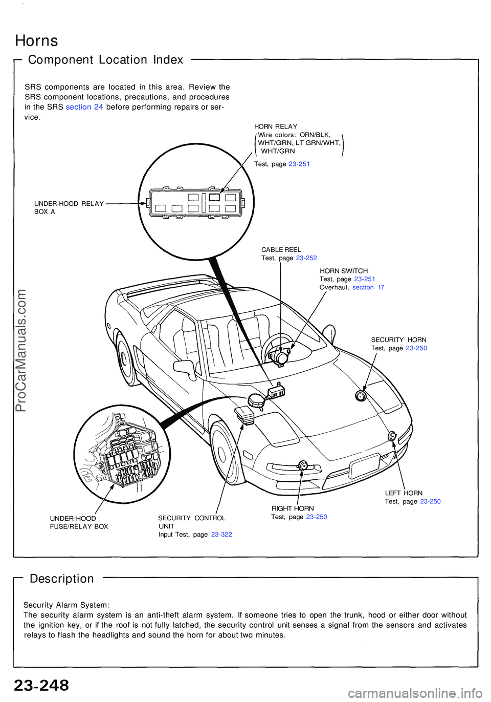
Horns
Componen t Locatio n Inde x
SRS component s ar e locate d i n thi s area . Revie w th e
SR S componen t locations , precautions , an d procedure s
i n th e SR S sectio n 24 befor e performin g repair s o r ser -
vice .
UNDER-HOO D RELA YBOX A
HOR N SWITC HTest, pag e 23-25 1
Overhaul , sectio n 1 7
CABL
E REE L
Test , pag e 23-25 2
SECURITY HOR N
Test , pag e 23-25 0
UNDER-HOO DFUSE/RELAY BO X SECURIT
Y CONTRO LUNITInpu t Test , pag e 23-32 2
RIGHT HOR NTest, pag e 23-25 0 LEF
T HOR N
Test , pag e 23-25 0
Descriptio n
Security Alar m System :
Th e securit y alar m syste m is a n anti-thef t alar m system . I f someon e trie s t o ope n th e trunk , hoo d o r eithe r doo r withou t
th e ignitio n key , o r i f th e roo f i s no t full y latched , th e securit y contro l uni t sense s a signa l fro m th e sensor s an d activate s
relay s t o flas h th e headlight s an d soun d th e hor n fo r abou t tw o minutes .
HORN RELA Y
Wir e colors : ORN/BLK ,
WHT/GRN, L T GRN/WHT ,, WHT/GR N
Test, pag e 23-25 1
ProCarManuals.com
Page 1473 of 1503
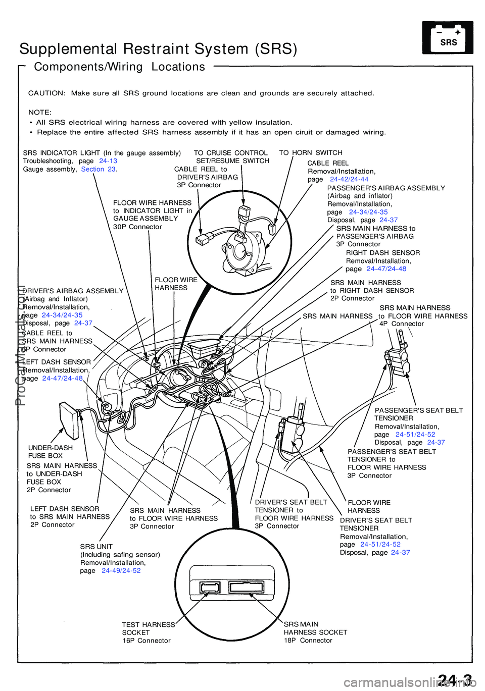
Supplemental Restrain t Syste m (SRS )
Components/Wirin g Location s
CAUTION: Mak e sur e al l SR S groun d location s ar e clea n an d ground s ar e securel y attached .
NOTE:
• Al l SR S electrica l wirin g harnes s ar e covere d wit h yello w insulation .
• Replac e th e entir e affecte d SR S harnes s assembl y i f i t ha s a n ope n cirui t o r damage d wiring .
SRS INDICATO R LIGH T (I n th e gaug e assembly ) T O CRUIS E CONTRO L
Troubleshooting , pag e 24-1 3 SET/RESUME SWITC H
Gaug e assembly , Sectio n 23 . CABL E REE L t o
DRIVER' S AIRBA G
3P Connecto r
TO HOR N SWITC H
DRIVER' S AIRBA G ASSEMBL Y
(Airba g an d Inflator )
Removal/Installation ,page 24-34/24-3 5Disposal, pag e 24-3 7
CABL E REE L t oSR S MAI N HARNES S6P Connecto r
LEFT DAS H SENSO RRemoval/Installation ,page 24-47/24-4 8
CABLE REE LRemoval/Installation ,page 24-42/24-4 4
PASSENGER' S AIRBA G ASSEMBL Y
(Airba g an d inflator )
Removal/Installation ,
pag e 24-34/24-3 5
Disposal , pag e 24-3 7
SRS MAI N HARNES S toPASSENGER' S AIRBA G
3 P Connecto r
RIGH T DAS H SENSO R
Removal/Installation ,
page 24-47/24-4 8
SRS MAI N HARNES S
t o RIGH T DAS H SENSO R
2 P Connecto r
SRS MAI N HARNES SSRS MAI N HARNES S t o FLOO R WIR E HARNES S
4 P Connecto r
UNDER-DAS H
FUS E BO X
SR S MAI N HARNES S
to UNDER-DAS HFUSE BO X
2 P Connecto r
LEF T DAS H SENSO R
t o SR S MAI N HARNES S
2 P Connecto r
SRS UNI T(Includin g safin g sensor )Removal/Installation ,
pag e 24-49/24-5 2 PASSENGER'
S SEA T BEL T
TENSIONE R
Removal/Installation ,
pag e 24-51/24-5 2
Disposal , pag e 24-3 7
PASSENGER' S SEA T BEL T
TENSIONE R t o
FLOO R WIR E HARNES S
3 P Connecto r
FLOO R WIR E
HARNES S
DRIVER' S SEA T BEL T
TENSIONE R
Removal/Installation ,page 24-51/24-5 2Disposal, pag e 24-3 7
TEST HARNES SSOCKET16P Connecto r
SRS MAI NHARNES S SOCKE T
18 P Connecto r
SR
S MAI N HARNES S
t o FLOO R WIR E HARNES S
3 P Connecto r DRIVER'
S SEA T BEL T
TENSIONE R t o
FLOO R WIR E HARNES S
3 P Connecto r
FLOO
R WIR E
HARNES S
FLOOR WIR E HARNES S
t o INDICATO R LIGH T i n
GAUGE ASSEMBL Y
30P Connecto r
ProCarManuals.com