Page 1200 of 1503
Sunlight Sensor
Removal
Protect the dashboard with a shop towel, then with a
small screwdriver, carefully pry the sunlight sensor out
of the dashboard and disconnect its connector.
SUNLIGHT
SENSOR
Test
Measure the voltage between the terminals with the sen-
sor out of direct sunlight.
• With the connector connected (probe the back of it):
1.4 ± 0.2 V
• With the connector disconnected: 0.1 - 0.2 VProCarManuals.com
Page 1201 of 1503
Heater Core Temperature Sensor
Removal
Disconnect the connector, remove the clamp and the
heater core temperature sensor.
CLAMP
HEATER CORE
TEMPERATURE
SENSOR
Compare the resistance reading between the terminals
of the heater core temperature sensor with specifica-
tions shown in the following graph: It should be within
specification.
NOTE: Dip the sensor in ice water, and measure the
resistance. Then pour hot water on the sensor, and
check for change in resistance.
Test
CAUTION: The sensor uses a thermistor which
can be damaged if high current is applied to it
during testing. Therefore, use a circuit tester
that puts out a measuring current of 1 mA or
less.ProCarManuals.com
Page 1202 of 1503
Evaporator Temperature Sensor
Removal
Give th e evaporato r temperatur e senso r a quarte r turn ,
then pul l ou t t o remov e it .
EVAPORATO RTEMPERATUR E SENSO R
Test
Compar e th e resistanc e readin g betwee n th e terminal s
of th e evaporato r temperatur e senso r wit h specificatio n
shown i n th e followin g graph : I t shoul d b e withi n
specification .
NOTE : Di p th e senso r i n ic e water , an d measur e th e
resistance . The n pou r ho t wate r o n th e sensor , an d
chec k fo r chang e i n resistance .
CAUTION : Th e senso r use s a thermisto r whic h
ca n b e damage d if hig h curren t i s applie d t o it
durin g testing . Therefore , us e a circui t teste r
tha t put s ou t a measurin g curren t o f 1 m A o r
less .
ProCarManuals.com
Page 1212 of 1503

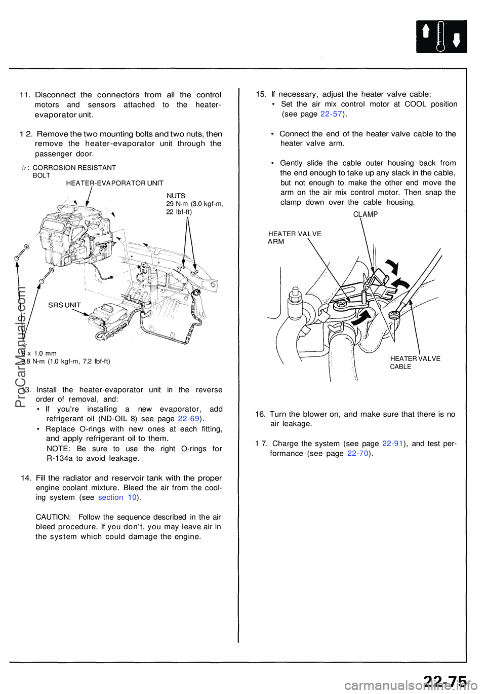
11. Disconnec t th e connector s fro m al l th e contro l
motors an d sensor s attache d t o th e heater -
evaporato r unit .
1 2 . Remov e th e tw o mountin g bolt s an d tw o nuts , the n
remov e th e heater-evaporato r uni t throug h th e
passenge r door .
CORROSIO N RESISTAN TBOLTHEATER-EVAPORATO R UNIT
NUT S29 N- m (3. 0 kgf-m ,
2 2 Ibf-ft )
6 x 1. 0 m m9.8 N- m (1. 0 kgf-m , 7. 2 Ibf-ft )
13. Instal l th e heater-evaporato r uni t i n th e revers e
orde r of removal , and :
• I f you'r e installin g a ne w evaporator , ad d
refrigeran t oi l (ND-OI L 8 ) se e pag e 22-69 ).
• Replac e O-ring s wit h ne w one s a t eac h fitting ,
and appl y refrigeran t oi l t o them .
NOTE : B e sur e t o us e th e righ t O-ring s fo r
R-134 a t o avoi d leakage .
14. Fil l th e radiato r an d reservoi r tan k wit h th e prope r
engine coolan t mixture . Blee d th e ai r fro m th e cool -
in g syste m (se e sectio n 10 ).
CAUTION : Follo w th e sequenc e describe d in th e ai r
blee d procedure . I f you don't , yo u ma y leav e ai r i n
th e syste m whic h coul d damag e th e engine .
15. I f necessary , adjus t th e heate r valv e cable :
• Se t th e ai r mi x contro l moto r a t COO L positio n
(se e pag e 22-57 ).
• Connec t th e en d o f th e heate r valv e cabl e t o th e
heate r valv e arm .
• Gentl y slid e th e cabl e oute r housin g bac k fro m
the en d enoug h to tak e u p an y slac k in th e cable ,
but no t enoug h t o mak e th e othe r en d mov e th e
ar m o n th e ai r mi x contro l motor . The n sna p th e
clam p dow n ove r th e cabl e housing .
CLAMP
HEATE R VALV EARM
HEATE R VALV ECABLE
16. Tur n th e blowe r on , an d mak e sur e tha t ther e is n o
air leakage .
1 7 . Charg e th e syste m (se e pag e 22-91 ), an d tes t per -
formanc e (se e pag e 22-70 ).
SR S UNI T
ProCarManuals.com
Page 1261 of 1503

Description ——————————————————\
——————————————————\
———
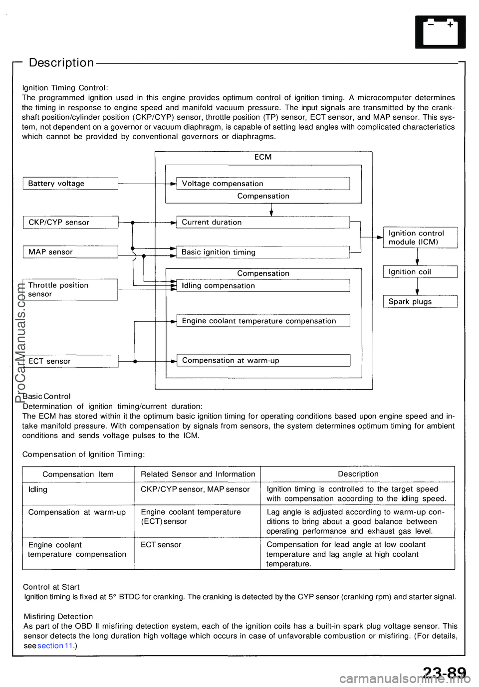
Ignition Timin g Control :
Th e programme d ignitio n use d i n thi s engin e provide s optimu m contro l o f ignitio n timing . A microcompute r determine s
th e timin g i n respons e t o engin e spee d an d manifol d vacuu m pressure . Th e inpu t signal s ar e transmitte d b y th e crank -
shaf t position/cylinde r positio n (CKP/CYP ) sensor , throttl e positio n (TP ) sensor , EC T sensor , an d MA P sensor . Thi s sys -
tem , no t dependen t o n a governo r o r vacuu m diaphragm , i s capabl e o f settin g lea d angle s wit h complicate d characteristic s
whic h canno t b e provide d b y conventiona l governor s o r diaphragms .
Basi c Contro l
Determinatio n of ignitio n timing/curren t duration :
Th e EC M ha s store d withi n i t th e optimu m basi c ignitio n timin g fo r operatin g condition s base d upo n engin e spee d an d in -
tak e manifol d pressure . Wit h compensatio n b y signal s fro m sensors , th e syste m determine s optimu m timin g fo r ambien t
condition s an d send s voltag e pulse s t o th e ICM .
Compensatio n o f Ignitio n Timing :
Compensatio n Ite m
Idlin g
Compensatio n a t warm-u p
Engin e coolan t
temperatur e compensatio nRelate
d Senso r an d Informatio n
CKP/CY P sensor , MA P senso r
Engin e coolan t temperatur e
(ECT) senso r
ECT senso r Descriptio
n
Ignitio n timin g i s controlle d t o th e targe t spee d
wit h compensatio n accordin g t o th e idlin g speed .
La g angl e i s adjuste d accordin g t o warm-u p con -
dition s t o brin g abou t a goo d balanc e betwee n
operatin g performanc e an d exhaus t ga s level .
Compensatio n fo r lea d angl e a t low coolan t
temperatur e an d la g angl e a t hig h coolan t
temperature .
Contro l a t Star t
Ignitio n timin g is fixe d a t 5 ° BTD C fo r cranking . Th e crankin g is detecte d b y th e CY P senso r (crankin g rpm ) an d starte r signal .
Misfirin g Detectio n
A s par t o f th e OB D II misfirin g detectio n system , eac h o f th e ignitio n coil s ha s a built-i n spar k plu g voltag e sensor . Thi s
senso r detect s th e lon g duratio n hig h voltag e whic h occur s i n cas e o f unfavorabl e combustio n o r misfiring . (Fo r details ,
se e sectio n 11 .)
ProCarManuals.com
Page 1282 of 1503

Radiator and Condenser Fan Controls
Description
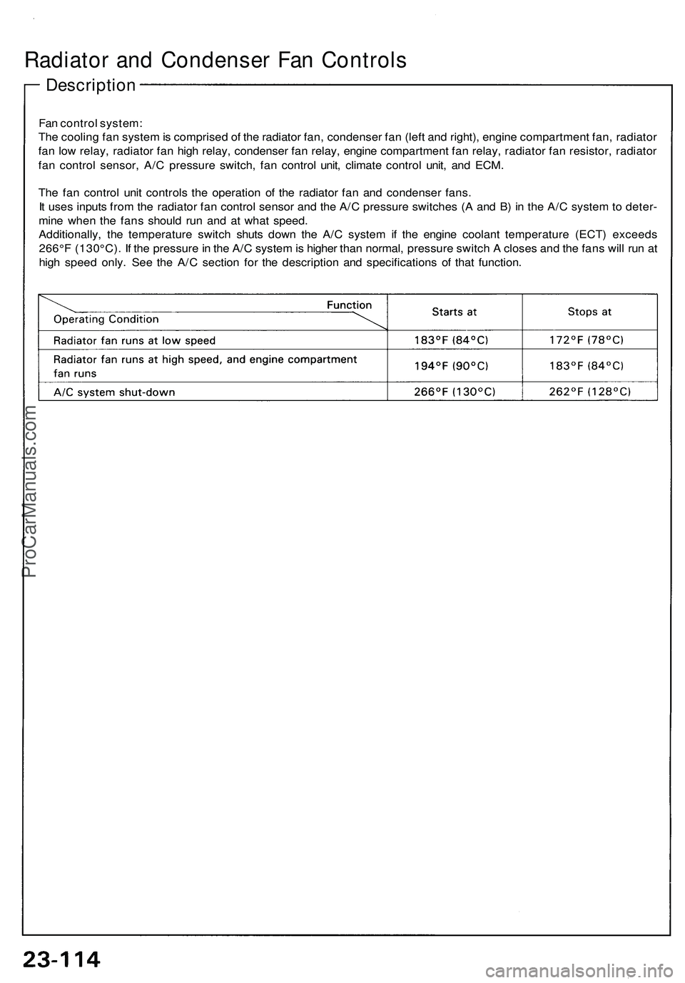
Fan control system:
The cooling fan system is comprised of the radiator fan, condenser fan (left and right), engine compartment fan, radiator
fan low relay, radiator fan high relay, condenser fan relay, engine compartment fan relay, radiator fan resistor, radiator
fan control sensor, A/C pressure switch, fan control unit, climate control unit, and ECM.
The fan control unit controls the operation of the radiator fan and condenser fans.
It uses inputs from the radiator fan control sensor and the A/C pressure switches (A and B) in the A/C system to deter-
mine when the fans should run and at what speed.
Additionally, the temperature switch shuts down the A/C system if the engine coolant temperature (ECT) exceeds
266°F (130°C). If the pressure in the A/C system is higher than normal, pressure switch A closes and the fans will run at
high speed only. See the A/C section for the description and specifications of that function.ProCarManuals.com
Page 1284 of 1503
Radiator and Condenser Fan Controls
Control Unit Terminals
THROTTLE VALVE CONTROL
MOTOR RELAY
Wire
Terminal Color
Connects to
1
2
3
4
5
6
7
8
9
10
11
12
-
LT GRN
GRY/BLK
BLU/RED
BLK
BRN/BLK
GRN
—
ORN/BLU
BLU/BLK
YEL/BLK
GRN/BLK
Not used
Radiator fan control sensor
Climate control unit
Radiator fan high and engine
compartment fan relays coil
Ground (G401, G402, G403)
A/C triple pressure switch A
Radiator fan control sensor
Not used
Condenser fan relay coil
ECM
(ACS)
IG2 (Power supply)
Radiator fan low relay coil
1. Disconnect the 3P connector from the resistor.
3P CONNECTOR
RADIATOR
FAN
RESISTOR
NOT USED
2. Using an ohmmeter, measure resistance between
the A and B terminals. Replace the resistor if the
resistance is not within specifications.
NOTE: Resistance will vary with the resistor
temperature; specifications are at 68°F (20°C).
Radiator Fan Resistor
Resistance: 0.54—0.66 ohms
Radiator Fan Resistor TestProCarManuals.com
Page 1288 of 1503
Radiator an d Condense r Fa n Control s
Radiator Fa n Contro l Senso r Tes t
NOTE : Blee d ai r fro m th e coolin g syste m afte r install -
in g th e radiato r fa n contro l senso r (se e sectio n 10 ).
1 . Remov e th e radiato r fa n contro l senso r fro m th e
thermosta t cover .
2 . Suspen d th e radiato r fa n contro l senso r i n a con -
taine r o f coolan t a s shown .
THERMOMETE R
RADIATOR FA N
CONTRO L SENSO R
ENGIN E
3. Hea t th e coolant , an d chec k coolan t temperatur e
wit h a thermomete r (se e tabl e below) .
4 . Measur e th e resistanc e betwee n th e A an d B ter -
minal s accordin g t o th e table .
5 . I f unabl e t o obtai n th e abov e readings , replac e th e
radiato r fa n contro l sensor .
ProCarManuals.com