Page 831 of 1202

SA116-01
N00185
SST
SA3199
SST
SA3200
SST
SST
SA3201
SST SA-14
- SUSPENSION AND AXLEFRONT AXLE HUB
1996 TERCEL (RM440U)
REASSEMBLY
1. INSTALL BEARING
(a) Using SST and a press, install a new bearing to the steer-
ing knuckle.
SST 09608-10010
NOTICE:
If the inner race and balls come loose from the bearing out-
er race, be sure to install them on the same side as before.
(b) Using snap ring pliers, install the snap ring.
2. INSTALL OUTER OIL SEAL
(a) Using SST and a hammer, install a new outer oil seal.
SST 09608-10010
(b) Coat the oil seal lip with MP grease.
3. INSTALL DUST COVER
(a) Place the dust cover on the steering knuckle.
(b) Using a torx wrench (T30), tighten the 3 bolts.
Torque: 8.3 N´m (85 kgf´cm, 74 in.´lbf)
4. INSTALL AXLE HUB
Using SST and a press, install the axle hub.
SST 09608-10010, 09950-60010 (09951-00610)
5. INSTALL LOWER BALL JOINT
(a) Install the lower ball joint and tighten the nut.
Torque: 98 N´m (1,000 kgf´cm, 72 ft´lbf)
(b) Install a new clip.
6. INSTALL INNER OIL SEAL
(a) Using SST and a hammer, install a new inner oil seal.
SST 09608-10010
(b) Coat the oil seal lip with MP grease.
Page 835 of 1202

SA128-02
FA1535
SST
F03986
SA-18
- SUSPENSION AND AXLEFRONT DRIVE SHAFT
1996 TERCEL (RM440U)
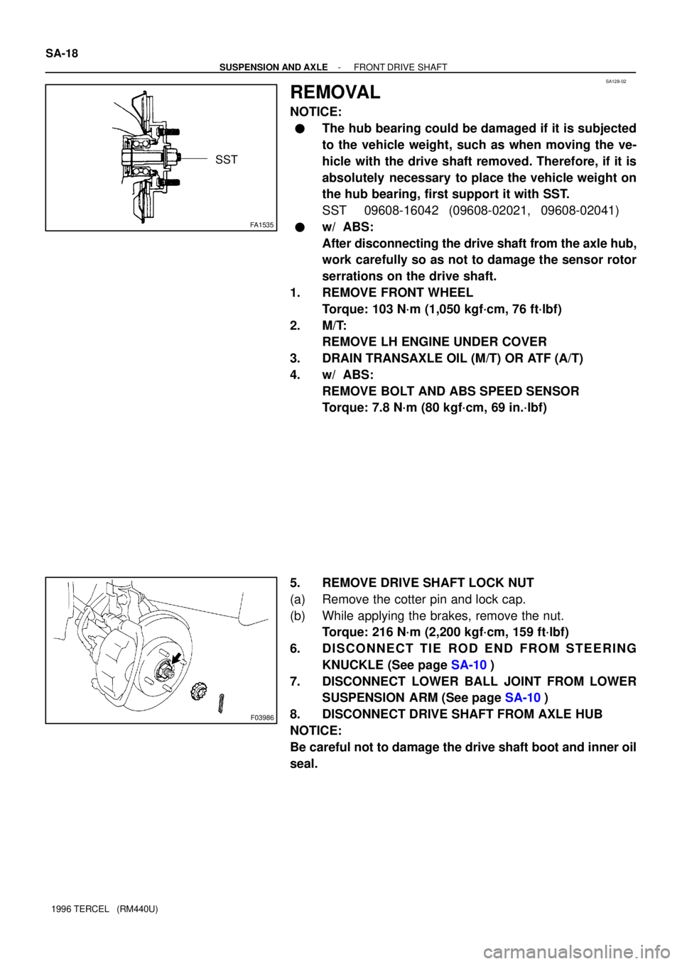
REMOVAL
NOTICE:
�The hub bearing could be damaged if it is subjected
to the vehicle weight, such as when moving the ve-
hicle with the drive shaft removed. Therefore, if it is
absolutely necessary to place the vehicle weight on
the hub bearing, first support it with SST.
SST 09608-16042 (09608-02021, 09608-02041)
�w/ ABS:
After disconnecting the drive shaft from the axle hub,
work carefully so as not to damage the sensor rotor
serrations on the drive shaft.
1. REMOVE FRONT WHEEL
Torque: 103 N´m (1,050 kgf´cm, 76 ft´lbf)
2. M/T:
REMOVE LH ENGINE UNDER COVER
3. DRAIN TRANSAXLE OIL (M/T) OR ATF (A/T)
4. w/ ABS:
REMOVE BOLT AND ABS SPEED SENSOR
Torque: 7.8 N´m (80 kgf´cm, 69 in.´lbf)
5. REMOVE DRIVE SHAFT LOCK NUT
(a) Remove the cotter pin and lock cap.
(b) While applying the brakes, remove the nut.
Torque: 216 N´m (2,200 kgf´cm, 159 ft´lbf)
6. DISCONNECT TIE ROD END FROM STEERING
KNUCKLE (See page SA-10)
7. DISCONNECT LOWER BALL JOINT FROM LOWER
SUSPENSION ARM (See page SA-10)
8. DISCONNECT DRIVE SHAFT FROM AXLE HUB
NOTICE:
Be careful not to damage the drive shaft boot and inner oil
seal.
Page 842 of 1202
SA1W8-02
- SUSPENSION AND AXLEFRONT SHOCK ABSORBER
SA-25
1996 TERCEL (RM440U)
REMOVAL
1. REMOVE FRONT WHEEL
Torque: 103 N´m (1,050 kgf´cm, 76 ft´lbf)
2. REMOVE FLEXIBLE HOSE
Remove the bolt and disconnect the flexible hose from the shock absorber.
Torque: 29 N´m (300 kgf´cm, 22 ft´lbf)
3. w/ ABS:
DISCONNECT ABS SPEED SENSOR WIRE HARNESS
Remove the bolt and disconnect the ABS speed sensor wire harness from the shock absorber.
Torque: 5.4 N´m (55 kgf´cm, 48 in.´lbf)
4. DISCONNECT SHOCK ABSORBER FROM STEERING KNUCKLE
Remove the 2 nuts and bolts and disconnect the shock absorber from steering knuckle,
Torque: 245 N´m (2,500 kgf´cm, 181 ft´lbf)
HINT:
Coat the nut's threads with engine oil.
5. REMOVE SHOCK ABSORBER AND COIL SPRING
(a) Remove the 3/4 nuts on the upper side of the shock absorber.
Torque: 39 N´m (400 kgf´cm, 29 ft´lbf)
(b) Remove the shock absorber with the coil spring.
Page 852 of 1202
SA11K-01
SA3121
SST
- SUSPENSION AND AXLEFRONT LOWER BALL JOINT
SA-35
1996 TERCEL (RM440U)
REMOVAL
1. REMOVE STEERING KNUCKLE WITH AXLE HUB
(See page SA-10)
2. REMOVE LOWER BALL JOINT
(a) Remove the clip and nut.
Torque: 98 N´m (1,000 kgf´cm, 72 ft´lbf)
(b) Using SST, remove the lower ball joint.
SST 09628-6201 1
Page 895 of 1202
BR0S5-06
R04569
R04570
BR-42
- BRAKEFRONT SPEED SENSOR
1996 TERCEL (RM440U)
REMOVAL
1. DISCONNECT SPEED SENSOR CONNECTOR
(a) Remove the fender liner.
(b) Disconnect the speed sensor connector.
2. REMOVE SPEED SENSOR
(a) Remove the 2 clamp bolts and a clip holding the sensor
harness to the body and shock absorber.
Torque: 5.0 N´m (51 kgf´cm, 44 in.´lbf)
(b) Remove the bolt and speed sensor from the steering
knuckle.
Torque: 8.0 N´m (82 kgf´cm, 71 in.´lbf)
Page 900 of 1202
SR05M-03
- STEERINGSTEERING SYSTEM
SR-1
921 Author�: Date�:
1996 TERCEL (RM440U)
STEERING SYSTEM
PRECAUTION
�Care must be taken to replace parts properly because they could affect the performance of the
steering system and result in a driving hazard.
�The TERCEL is equipped with SRS (Supplemental Restraint System) such as the driver airbag
and front passenger airbag. Failure to carry out service operation in the correct sequence could
cause the SRS to unexpectedly deployed during servicing, possibly leading to a serious acci-
dent. Before servicing (including removal or installation of parts, inspection or replacement),
be sure to read the precautionary notices in the RS section.
Page 901 of 1202

SR05N-06
SR-2
- STEERINGTROUBLESHOOTING
922 Author�: Date�:
1996 TERCEL (RM440U)
TROUBLESHOOTING
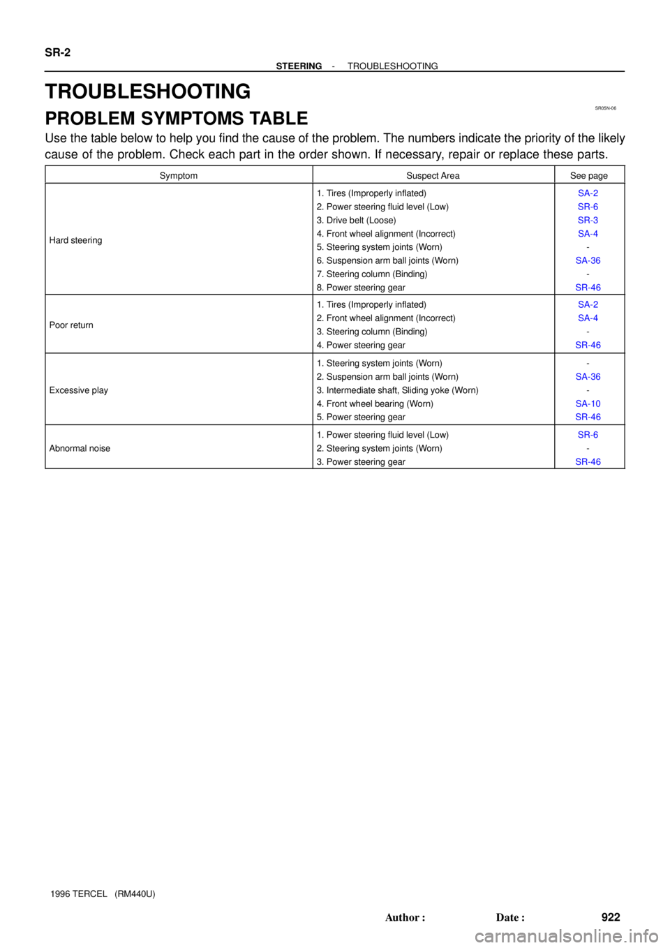
PROBLEM SYMPTOMS TABLE
Use the table below to help you find the cause of the problem. The numbers indicate the priority of the likely
cause of the problem. Check each part in the order shown. If necessary, repair or replace these parts.
SymptomSuspect AreaSee page
Hard steering
1. Tires (Improperly inflated)
2. Power steering fluid level (Low)
3. Drive belt (Loose)
4. Front wheel alignment (Incorrect)
5. Steering system joints (Worn)
6. Suspension arm ball joints (Worn)
7. Steering column (Binding)
8. Power steering gearSA-2
SR-6
SR-3
SA-4
-
SA-36
-
SR-46
Poor return
1. Tires (Improperly inflated)
2. Front wheel alignment (Incorrect)
3. Steering column (Binding)
4. Power steering gearSA-2
SA-4
-
SR-46
Excessive play
1. Steering system joints (Worn)
2. Suspension arm ball joints (Worn)
3. Intermediate shaft, Sliding yoke (Worn)
4. Front wheel bearing (Worn)
5. Power steering gear-
SA-36
-
SA-10
SR-46
Abnormal noise
1. Power steering fluid level (Low)
2. Steering system joints (Worn)
3. Power steering gearSR-6
-
SR-46
Page 902 of 1202

Z00038
DENSO BorroughsSR1F5-01
CH0087
CORRECT
WRONG
WRONG
R11541
PS Vane
Pump
CORRECTWRONG C
D
E
F
- STEERINGDRIVE BELT
SR-3
923 Author�: Date�:
1996 TERCEL (RM440U)
DRIVE BELT
INSPECTION
1. CHECK DRIVE BELT TENSION
Using a belt tension gauge, measure the belt tension.
Belt tension gauge:
DENSO BTG-20 (95506-00020) or
Borroughs No. BT-33-73F
Drive belt tension:
New belt: 140 - 180 lbf
Used belt: 80 - 120 lbf
NOTICE:
After installing the belt, check that it fits properly in the
ribbed grooves.
HINT:
�ºNew beltº refers to a belt which has been used less than
5 minutes on a running engine.
�ºUsed beltº refers to a belt which has been used on a run-
ning engine for 5 minutes or more.
2. VEHICLES WITH BELT TENSION ADJUSTING BOLT:
ADJUST DRIVE BELT TENSION
(a) Loosen the bolts A and B.
(b) Loosen the lock nuts D and E.
(c) Adjust adjusting bolt F so that its protrusion above nut C
is ± 0 mm (0 in.).
(d) Fix nut C using lock nut D.
(e) Push up the PS pump body so that there is no free play
in the belt. Turn adjusting bolt F to obtain the play in the
correct belt tension as specified above.
NOTICE:
Ensure that the pump body and nut C are positioned cor-
rectly, as shown before turning bolt F to adjust the bet ten-
sion.
(f) Torque the bolt A.
Torque: 43 N´m (440 kgf´cm, 32 ft´lbf)