Page 544 of 1202

Fuel Filter
(On Vehicle) SST (Union)
- MFIINJECTOR
MF-19
1996 TERCEL (RM440U)
INSPECTION
1. INSPECT INJECTOR INJECTION
CAUTION:
Keep injector clean of sp")
SF1PV-02
P20397
Union Bolt
Gasket
SST (Hose)
Fuel Filter
(On Vehicle) SST (Union)
- MFIINJECTOR
MF-19
1996 TERCEL (RM440U)
INSPECTION
1. INSPECT INJECTOR INJECTION
CAUTION:
Keep injector clean of sparks during the test.
(a) Remove the union bolt and 2 gaskets, and disconnect the
fuel inlet hose from the fuel filter outlet.
(b) Connect SST (union and hose) to the fuel filter outlet with
2 gaskets and union bolts.
SST 09268-41046 (90405-09015)
Torque: 29 N´m (290 kgf´cm, 22 ft´lbf)
(c) Remove the pressure regulator from the delivery pipe
(See page MF-14).
(d) Install a O-ring to the fuel inlet of pressure regulator.
(e) Connect SST (hose) to the fuel inlet of the pressure regu-
lator with SST (union) and the 2 bolts.
SST 09268-41046 (09268-41091)
Torque: 8.0 N´m (80 kgf´cm, 69 ft´lbf)
(f) Connect the fuel return hose to the fuel outlet of the pres-
sure regulator.
CAUTION:
Install a suitable vinyl hose onto the injector to prevent
gasoline from splashing out.
(g) Remove the fuse cover on the instrument panel.
Page 545 of 1202

SST (Union)
O-Ring
SST
(Clamp)
Vinyl Tube
P19552
TOYOTA Hand-Held Tester
DLC3
FI3211
SST
(Wire)
Connect
FI1676
MF-20
- MFIINJECTOR
1996 TERCEL (RM440U)
(h) Install the grommet and")
Z14695
SST (Hose)
SST (Union)
O-Ring
SST
(Clamp)
Vinyl Tube
P19552
TOYOTA Hand-Held Tester
DLC3
FI3211
SST
(Wire)
Connect
FI1676
MF-20
- MFIINJECTOR
1996 TERCEL (RM440U)
(h) Install the grommet and a O-ring to the injector.
(i) Connect SST (union and hose) to the injector, and hold
the injector and union with SST (clamp).
SST 09368-41046
(j) Put the injector into the graduated cylinder.
CAUTION:
Install a suitable vinyl hose onto the injector to prevent
gasoline from splashing out.
(k) Remove the fuse cover on the instrument panel.
(l) Connect the TOYOTA hand-held tester to the DLC3.
(m) Turn the ignition switch ON and TOYOTA hand-held tes-
ter main switch ON.
NOTICE:
Do not start the engine.
(n) Select the active test mode on the TOYOTA hand-held
tester.
(o) Please refer to the TOYOTA hand-held tester operator's
manual for further details.
(p) If you have no TOYOTA hand-held tester, connect the
positive (+) and negative (-) leads from the battery to the
fuel pump connector (See page MF-5).
(q) Connect SST (wire) to the injector and battery for 15 se-
conds, and measure the injection volume with a gra-
duated cylinder. Test each injector 2 or 3 times.
SST 09842-30070
Volume:
39 - 49 cm
3 (2.4 - 3.0 cu in.) per 15 sec.
Difference between each injector:
5 cm
3 (0.3 cu in.) or less
If the injection volume is not as specified, replace the injector.
2. INSPECT LEAKAGE
(a) In the condition above, disconnect the tester probes of
SST (wire) from the battery and check the fuel leakage
from the injector.
SST 09842-30070
Fuel drop:
1 drop or less per 3 minutes
(b) Disconnect the negative (-) terminal cable from the bat-
tery.
(c) Remove the SST.
Page 581 of 1202
P19552
TOYOTA Hand-Held Tester
DLC3SF0WH-03
MF-56
- MFIFUEL CUT RPM
580 Author�: Date�:
1996 TERCEL (RM440U)
FUEL CUT RPM
INSPECTION
1. WARM UP ENGINE
Allow the engine to warm up to normal operating temperature.
2. CONNECT TOYOTA HAND-HELD TESTER OR OBDII
SCAN TOOL
(a) Remove the fuse cover on the instrument panel.
(b) Connect the TOYOTA hand-held tester or OBDII scan
tool to the DLC3.
(c) Please refer to the TOYOTA hand-held tester or OBDII
scan tool operator's manual for futher details.
3. INSPECT FUEL CUT OFF PRM
(a) Increase the engine speed to at least 2,500 rpm.
(b) Use a sound scope to check for injector operating noise.
(c) Check that when the throttle lever is released, injector op-
eration noise stops momentarily and then resumes.
HINT:
Measure with the A/C OFF.
Fuel return rpm: 900 rpm
4. DISCONNECT TOYOTA HAND- HELD TESTER OR
OBDII SCAN TOOL
Page 913 of 1202

4. REMOVE CENTER UPPER INSTRUMENT CLUSTER
FINISH PANEL
(a) Remove the screw.
(b) Remove the 3 cl")
R12213
A
B
Matchmarks
Manual Steering: SR-14
- STEERINGNON-TIL T STEERING COLUMN
1996 TERCEL (RM440U)
4. REMOVE CENTER UPPER INSTRUMENT CLUSTER
FINISH PANEL
(a) Remove the screw.
(b) Remove the 3 clips.
5. REMOVE UPPER AND LOWER COLUMN COVERS
Remove the 6 screws.
6. REMOVE FRONT DOOR SCUFF PLATE AND COWL
SIDE TRIM
Remove the clip and trim.
7. REMOVE LOWER INSTRUMENT COVER AND
INSTRUMENT PANEL LOWER PAD INSERT
(a) Remove the 2 opening covers from the instrument cover.
(b) Remove the 2 screws and disconnect the hood lock re-
lease lever from the instrument cover.
(c) Remove the 4 panel cover set bolts.
(d) Remove the lower pad insert from the instrument cover.
8. REMOVE NO.2 HEATER TO REGISTER DUCT
(a) Disconnect the junction block No.1 with the 3 screws.
(b) Remove the clip.
9. REMOVE COMBINATION SWITCH WITH SPIRAL
CABLE
(a) Disconnect the 3 connectors.
(b) w/ Airbag:
Disconnect the airbag connector.
(c) w/ Airbag:
Remove the 3 screws.
10. REMOVE SPIRAL CABLE (See page BE-14)
NOTICE:
Do not disassemble the cable or apply oil to it.
11. REMOVE COLUMN HOLE COVER
Remove the 4 nuts.
12. DISCONNECT SLIDING YOKE
(a) Place matchmarks on the yoke and steering pinion shaft/
control valve shaft.
(b) Loosen bolt A and remove bolt B.
Page 983 of 1202
RS0AZ-06
N12255
- SUPPLEMENTAL RESTRAINT SYSTEMFRONT PASSENGER AIRBAG ASSEMBLY
RS-21
1996 TERCEL (RM440U)
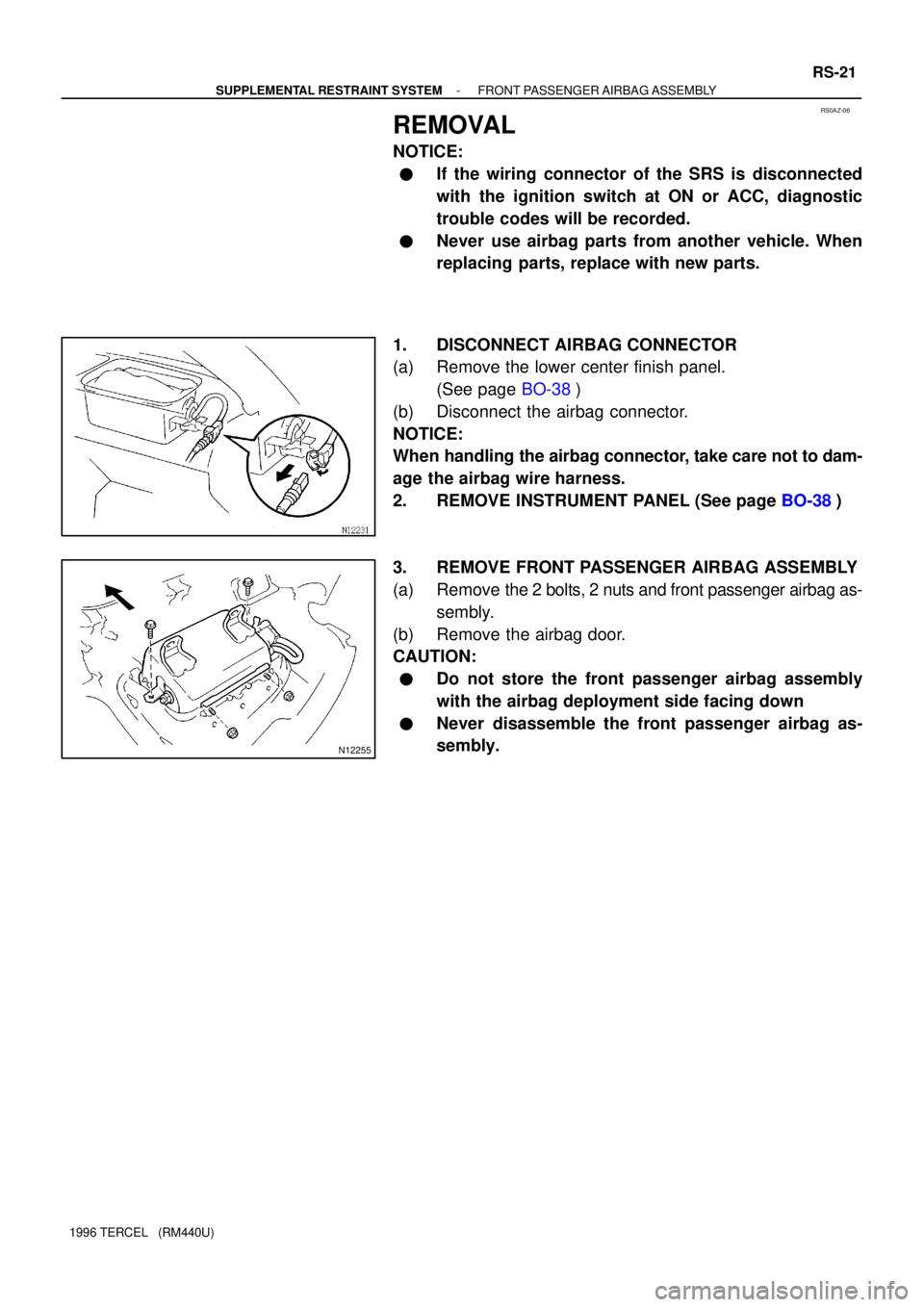
REMOVAL
NOTICE:
�If the wiring connector of the SRS is disconnected
with the ignition switch at ON or ACC, diagnostic
trouble codes will be recorded.
�Never use airbag parts from another vehicle. When
replacing parts, replace with new parts.
1. DISCONNECT AIRBAG CONNECTOR
(a) Remove the lower center finish panel.
(See page BO-38)
(b) Disconnect the airbag connector.
NOTICE:
When handling the airbag connector, take care not to dam-
age the airbag wire harness.
2. REMOVE INSTRUMENT PANEL (See page BO-38)
3. REMOVE FRONT PASSENGER AIRBAG ASSEMBLY
(a) Remove the 2 bolts, 2 nuts and front passenger airbag as-
sembly.
(b) Remove the airbag door.
CAUTION:
�Do not store the front passenger airbag assembly
with the airbag deployment side facing down
�Never disassemble the front passenger airbag as-
sembly.
Page 984 of 1202
RS0QD-02
H05490
H17547
H06090
Intrument Panel Reinforcement
RS-22
- SUPPLEMENTAL RESTRAINT SYSTEMFRONT PASSENGER AIRBAG ASSEMBLY
1996 TERCEL (RM440U)
INSPECTION
1. VEHICLE NOT INVOLVED IN COLLISION
(a) Do a diagnostic system check (See page DI-148).
(b) Do a visual check which includes the following items with
the front passenger airbag assembly installed in the ve-
hicle.
Check for cuts, minute cracks in or marked discoloration
of the front passenger airbag door.
2. VEHICLE INVOLVED IN COLLISION AND AIRBAG IS
NOT DEPLOYED
(a) Do a diagnostic system check (Seee page DI-148).
(b) Do a visual check which includes the following items with
the front passenger airbag assembly removed from the
vehicle.
�Check for cuts and cracks in, or marked discolor-
ation of the front passenger airbag door.
�Check for cuts and cracks in wire harnesses, and for
chipping in connectors.
�Check for deformation of the instrument panel and
instrument panel reinforcement.
Page 985 of 1202

HINT:
�If the instrument panel or instrument panel reinforcement
is deformed, never repair it. Always")
H05490
- SUPPLEMENTAL RESTRAINT SYSTEMFRONT PASSENGER AIRBAG ASSEMBLY
RS-23
1996 TERCEL (RM440U)
HINT:
�If the instrument panel or instrument panel reinforcement
is deformed, never repair it. Always replace it with a new
one.
�There should be no interference between the instrument
panel and front passenger airbag door, or the glove
compartment door and front passenger airbag door. The
clearance should be uniform all the way around when the
new airbag assembly is installed on the instrument panel.
CAUTION:
For removal and installation of the front passenger airbag
assembly, see page RS-21 and RS-31, and be sure to fol-
low the correct procedure.
3. VEHICLE INVOLVED IN COLLISION AND AIRBAG IS
DEPLOYED
(a) Do a diagnostic system check (See page DI-148).
(b) Do a visual check which includes the following items with
the airbag assembly removed from the vehicle.
�Check for deformation of the instrument panel,
instrument panel reinforcement and glove compart-
ment door.
�Check for damage to the connector and wire har-
ness.
HINT:
�If the instrument panel or instrument panel reinforcement
is deformed, never repair it. Always replace it with a new
one.
�There should be no interference between the instrument
panel and front passenger airbag door, or the glove
compartment and front passenger airbag door. The clear-
ance should be uniform all the way around when the new
airbag assembly is installed on the instrument panel.
Page 1013 of 1202

(f) Connect the negative (-) lead from the battery to terminal
8.
(g) Di")
N12792
N12793
Junction Block Side BE-12
- BODY ELECTRICALIGNITION SWITCH AND KEY UNLOCK WARNING
SWITCH
1996 TERCEL (RM440U)
(f) Connect the negative (-) lead from the battery to terminal
8.
(g) Disconnect the negative (-) lead from the battery to termi-
nal 4.
(h) Check that the chime stops sounding.
If operation is not as specified, replace the relay.
4. INSPECT INTEGRATION RELAY CIRCUIT
Remove the relay from the instrument panel junction block and
inspect the connectors on the junction block side.
Tester connectionConditionSpecified condition
4 - GroundKey unlock warning switch OFFNo continuity
4 - GroundKey unlock warning switch ONContinuity
5 - GroundBuckle switch OFF
(Seat belt unfastened)No continuity
5 - GroundBuckle switch ON
(Seat belt fastened)Continuity
7 - GroundConstantContinuity
8 - GroundDriver's door courtesy switch OFFNo continuity
8 - GroundDriver's door courtesy switch ONContinuity
11 - GroundLight control switch OFFNo continuity
11 - GroundLight control switch TAIL or HEADContinuity
2 - GroundIgnition switch LOCK or ACCNo voltage
2 - GroundIgnition switch ONBattery positive voltage
3 - GroundConstantBattery positive voltage
9 - GroundIgnition switch LOCK or ACCNo voltage
9 - GroundIgnition switch ONBattery positive voltage
12 - GroundConstantBattery positive voltage
If the circuit is as specified, try replacing the relay with a new
one.
If the circuit is not as specified, inspect the circuits connected
to other parts.


INSPECTION
1. VEHICLE NOT INVOLVED IN COLLISION")