Page 495 of 1202
P20473
Mark
1,2 or 3
Mark
1,2 or 3
P20491
EM3445
- ENGINE MECHANICALCYLINDER BLOCK
EM-73
1996 TERCEL (RM440U)
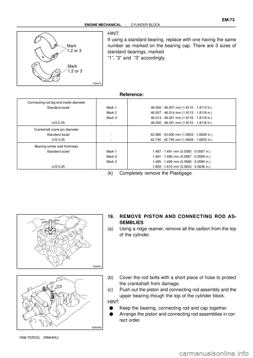
HINT:
If using a standard bearing, replace with one having the same
number as marked on the bearing cap. There are 3 sizes of
standard bearings, marked
º1º, º2º and º3º accordingly.
Reference:
Connecting rod big end inside diameter
Standard sized
U/S 0.25
Mark 1
Mark 2
Mark 3
-46.000 - 46.007 mm (1.8110 - 1.8113 in.)
46.007 - 46.014 mm (1.8113 - 1.8116 in.)
46.014 - 46.021 mm (1.8116 - 1.8118 in.)
46.000 - 46.021 mm (1.8110 - 1.8118 in.)
Crankshaft crank pin diameter
Standard sized
U/S 0.25
-
-42.985 - 43.000 mm (1.6923 - 1.6929 in.)
42.745 - 42.755 mm (1.6829 - 1.6833 in.)
Bearing center wall thickness
Standard sized
U/S 0.25
Mark 1
Mark 2
Mark 3
-1.487 - 1.491 mm (0.0585 - 0.0587 in.)
1.491 - 1.495 mm (0.0587 - 0.0589 in.)
1.495 - 1.499 mm (0.0589 - 0.0590 in.)
1.609 - 1.615 mm (0.0633 - 0.0636 in.)
(k) Completely remove the Plastigage.
19. REMOVE PISTON AND CONNECTING ROD AS-
SEMBLIES
(a) Using a ridge reamer, remove all the carbon from the top
of the cylinder.
(b) Cover the rod bolts with a short piece of hose to protect
the crankshaft from damage.
(c) Push out the piston and connecting rod assembly and the
upper bearing though the top of the cylinder block.
HINT:
�Keep the bearing, connecting rod and cap together.
�Arrange the piston and connecting rod assemblies in cor-
rect order.
Page 497 of 1202
P20488
EM9443
Plastigage
Z14291
4
810
6
2 159
73
EM9442
- ENGINE MECHANICALCYLINDER BLOCK
EM-75
1996 TERCEL (RM440U)
(d) Clean each main journal and bearing.
(e) Check each main journal and bearing for pitting and
scratches.
If the journal or bearing is damaged, replace the bearing.
If necessary, grind or replace the crankshaft.
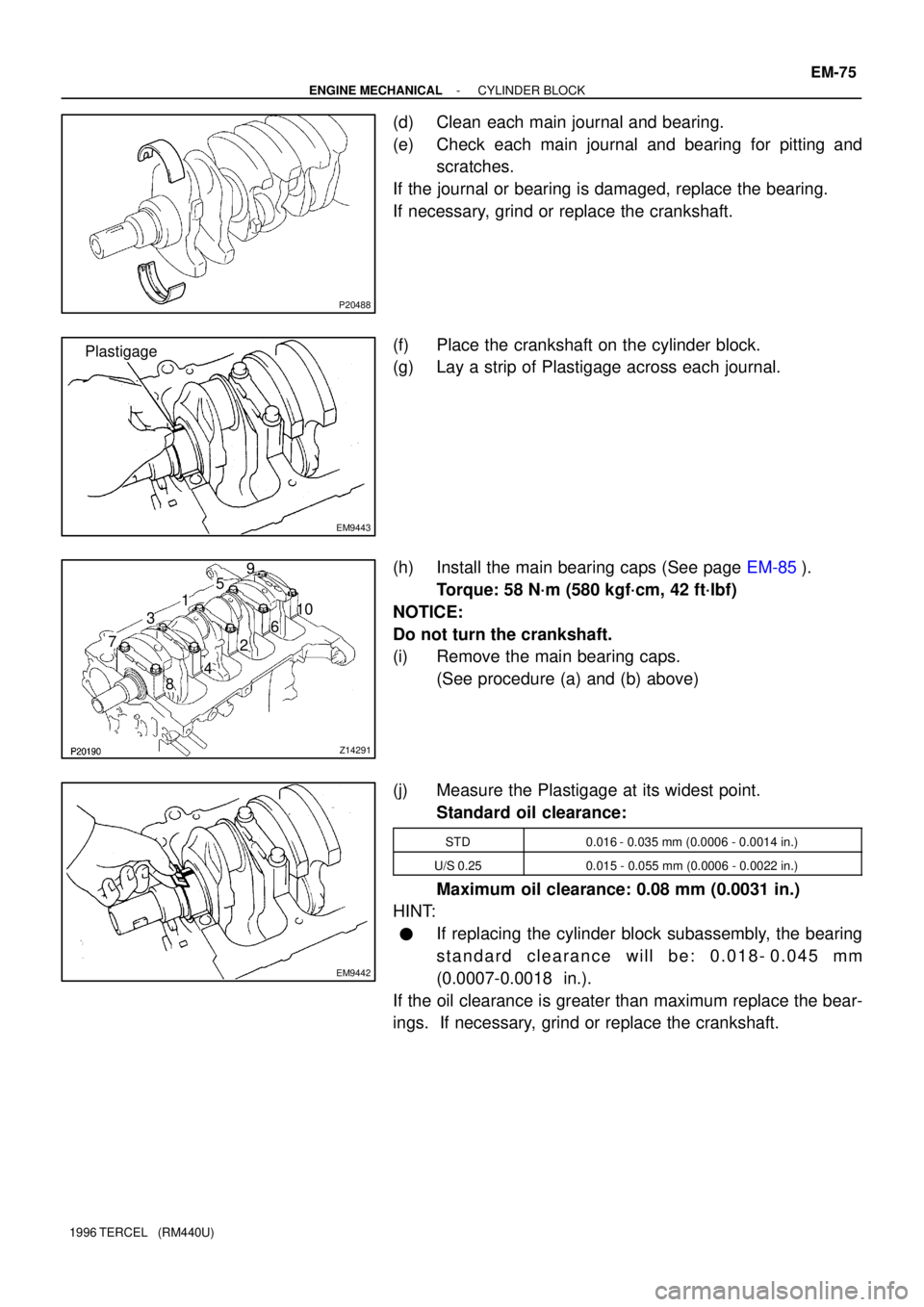
(f) Place the crankshaft on the cylinder block.
(g) Lay a strip of Plastigage across each journal.
(h) Install the main bearing caps (See page EM-85).
Torque: 58 N´m (580 kgf´cm, 42 ft´lbf)
NOTICE:
Do not turn the crankshaft.
(i) Remove the main bearing caps.
(See procedure (a) and (b) above)
(j) Measure the Plastigage at its widest point.
Standard oil clearance:
STD0.016 - 0.035 mm (0.0006 - 0.0014 in.)
U/S 0.250.015 - 0.055 mm (0.0006 - 0.0022 in.)
Maximum oil clearance: 0.08 mm (0.0031 in.)
HINT:
�If replacing the cylinder block subassembly, the bearing
standard clearance will be: 0.018- 0.045 mm
(0.0007-0.0018 in.).
If the oil clearance is greater than maximum replace the bear-
ings. If necessary, grind or replace the crankshaft.
Page 503 of 1202
P20540
P20527
Top of Cylinder Block
110 mm
(4.33 in.,)
EM7639
N00301
- ENGINE MECHANICALCYLINDER BLOCK
EM-81
1996 TERCEL (RM440U)
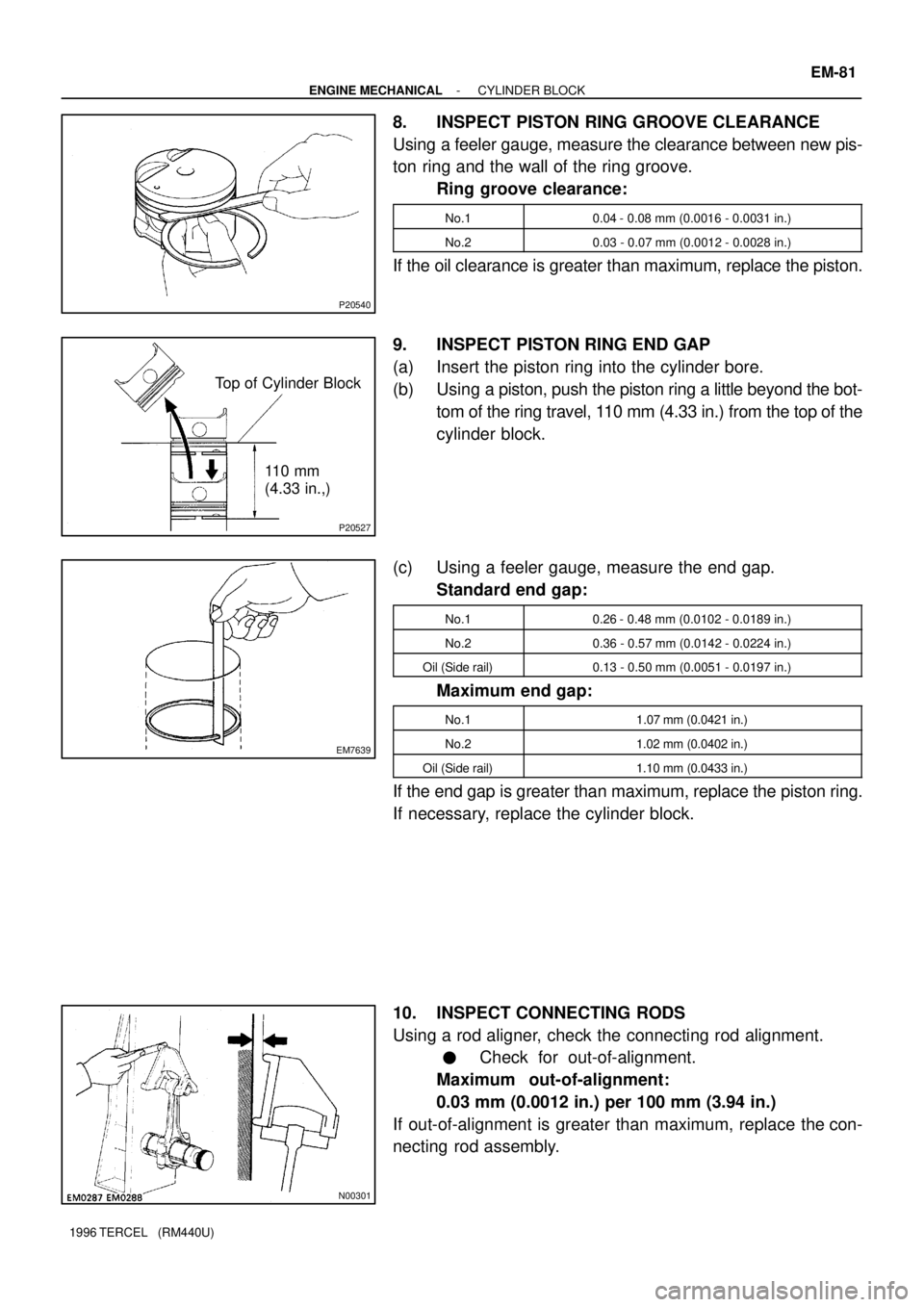
8. INSPECT PISTON RING GROOVE CLEARANCE
Using a feeler gauge, measure the clearance between new pis-
ton ring and the wall of the ring groove.
Ring groove clearance:
No.10.04 - 0.08 mm (0.0016 - 0.0031 in.)
No.20.03 - 0.07 mm (0.0012 - 0.0028 in.)
If the oil clearance is greater than maximum, replace the piston.
9. INSPECT PISTON RING END GAP
(a) Insert the piston ring into the cylinder bore.
(b) Using a piston, push the piston ring a little beyond the bot-
tom of the ring travel, 110 mm (4.33 in.) from the top of the
cylinder block.
(c) Using a feeler gauge, measure the end gap.
Standard end gap:
No.10.26 - 0.48 mm (0.0102 - 0.0189 in.)
No.20.36 - 0.57 mm (0.0142 - 0.0224 in.)
Oil (Side rail)0.13 - 0.50 mm (0.0051 - 0.0197 in.)
Maximum end gap:
No.11.07 mm (0.0421 in.)
No.21.02 mm (0.0402 in.)
Oil (Side rail)1.10 mm (0.0433 in.)
If the end gap is greater than maximum, replace the piston ring.
If necessary, replace the cylinder block.
10. INSPECT CONNECTING RODS
Using a rod aligner, check the connecting rod alignment.
�Check for out-of-alignment.
Maximum out-of-alignment:
0.03 mm (0.0012 in.) per 100 mm (3.94 in.)
If out-of-alignment is greater than maximum, replace the con-
necting rod assembly.
Page 507 of 1202
EM0JT-05
P20471
Front Mark
(Cavity)
Front Mark
(Protrusion)
Z08055
SST
Piston Pin
SSTSST
SST
SST
SST SST
P20549
P20560
1R
2R
- ENGINE MECHANICALCYLINDER BLOCK
EM-85
1996 TERCEL (RM440U)
REASSEMBLY
HINT:
�Thoroughly clean all parts to be assembled.
�Before installing the parts, apply new engine oil to all slid-
ing and rotating surfaces.
�Replace all gaskets, O-rings and oil seals with new parts.
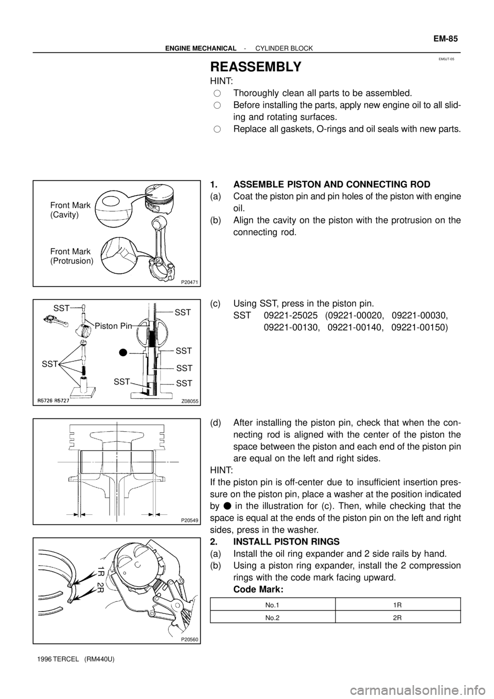
1. ASSEMBLE PISTON AND CONNECTING ROD
(a) Coat the piston pin and pin holes of the piston with engine
oil.
(b) Align the cavity on the piston with the protrusion on the
connecting rod.
(c) Using SST, press in the piston pin.
SST 09221-25025 (09221-00020, 09221-00030,
09221-00130, 09221-00140, 09221-00150)
(d) After installing the piston pin, check that when the con-
necting rod is aligned with the center of the piston the
space between the piston and each end of the piston pin
are equal on the left and right sides.
HINT:
If the piston pin is off-center due to insufficient insertion pres-
sure on the piston pin, place a washer at the position indicated
by � in the illustration for (c). Then, while checking that the
space is equal at the ends of the piston pin on the left and right
sides, press in the washer.
2. INSTALL PISTON RINGS
(a) Install the oil ring expander and 2 side rails by hand.
(b) Using a piston ring expander, install the 2 compression
rings with the code mark facing upward.
Code Mark:
No.11R
No.22R
Page 527 of 1202
FI2553
SST
FI4429
Plug MF-2
- MFIMFI SYSTEM
526 Author�: Date�:
1996 TERCEL (RM440U)
(b) When installing the battery, be especially careful not to in-
correctly connect the positive (+) and negative (-) cables.
(c) Do not permit parts to receive a severe impact during re-
moval or installation. Handle all MFI parts carefully, espe-
cially the ECM.
(d) Do not be careless during troubleshooting as there are
numerous transistor circuits and contact with terminals
can cause further trouble.
(e) Do not open the ECM cover.
(f) When inspecting during rainy weather, take care to pre-
vent the entry of water. Also, when washing the engine
compartment, prevent water from getting on the MFI parts
and wiring connectors.
(g) Parts should be replaced as an assembly.
(h) Care is required when pulling out and inserting wiring con-
nectors.
(i) Release the lock and pull out the connector, pulling on the
connectors.
(j) Fully insert the connector and check that it is locked.
(k) When inspecting a connector with a volt/ohmmeter.
(l) Carefully take off the water-proofing rubber if it is a wa-
ter-proof type connector.
(m) Insert the tester probe into the connector from the wiring
side when checking the continuity, amperage or voltage.
(n) Do not apply unnecessary force to the terminal.
(o) After checking, install the water-proofing rubber securely
on the connector.
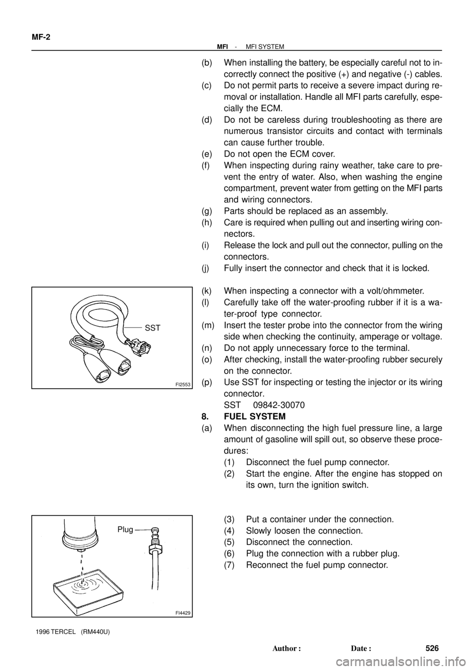
(p) Use SST for inspecting or testing the injector or its wiring
connector.
SST 09842-30070
8. FUEL SYSTEM
(a) When disconnecting the high fuel pressure line, a large
amount of gasoline will spill out, so observe these proce-
dures:
(1) Disconnect the fuel pump connector.
(2) Start the engine. After the engine has stopped on
its own, turn the ignition switch.
(3) Put a container under the connection.
(4) Slowly loosen the connection.
(5) Disconnect the connection.
(6) Plug the connection with a rubber plug.
(7) Reconnect the fuel pump connector.
Page 597 of 1202
CO0Y2-02
(b)
(a)
P20609
(c)(d)
P20754
Plug
(e)
P20755
A/T
(A)
P20610
Radiator Lower Hose
Radiator Lower Support CO-16
- COOLINGRADIATOR
1996 TERCEL (RM440U)
REMOVAL
1. REMOVE ENGINE UNDER COVERS
2. DRAIN ENGINE COOLANT
3. REMOVE RADIATOR RESERVOIR TANK ASSEMBLY
4. REMOVE RADIATOR ASSEMBLY
(a) Disconnect the No.1 cooling fan connector.
(b) w/ A/C:
Disconnect the No.2 cooling fan connector.
(c) Disconnect the radiator upper hose from the radiator.
(d) Disconnect the radiator lower hose from the water inlet.
(e) Disconnect the 2 A/T oil cooler hoses from the radiator.
HINT:
Plug the hose to prevent oil from escaping.
(f) Remove the 2 bolts and 2 upper radiator supports.
Torque: 12 N´m (120 kgf´cm, 9 ft´lbf)
HINT:
(A/T only):
After installation, check that the rubber cushion (A) of the sup-
port is not depressed.
(g) Remove the radiator assembly.
(h) Remove the 2 radiator lower supports and the lower ra-
diator hose.
Page 609 of 1202
CO0I9-04
P20884
CO-28
- COOLINGELECTRIC COOLING FAN
1996 TERCEL (RM440U)
REMOVAL
1. REMOVE NO.1 COOLING FAN
(a) Remove the engine under covers.
(b) Drain the engine coolant.
(c) Remove the air cleaner inlet.
(d) Remove the reservoir tank assembly.
(e) Remove the No.1 cooling fan.
(1) Disconnect the upper radiator hose from the radia-
tor.
(2) Disconnect the cooling fan connector.
(3) Remove the 2 bolts and cooling fan.
Torque: 7.0 N´m (70 kgf´cm, 61 in.´lbf)
2. REMOVE NO.2 COOLING FAN
(a) Disconnect the cooling fan connector.
(b) Remove the 3 bolts and cooling fan.
Torque: 7.0 N´m (70 kgf´cm, 61 in.´lbf)
Page 725 of 1202
Q06532
SST
Engine Side
Q06533
SST
Socket Wrench
N00174
SST
SST
Q06514
x5 MX-12
- MANUAL TRANSAXLEMANUAL TRANSAXLE ASSEMBLY
1996 TERCEL (RM440U)
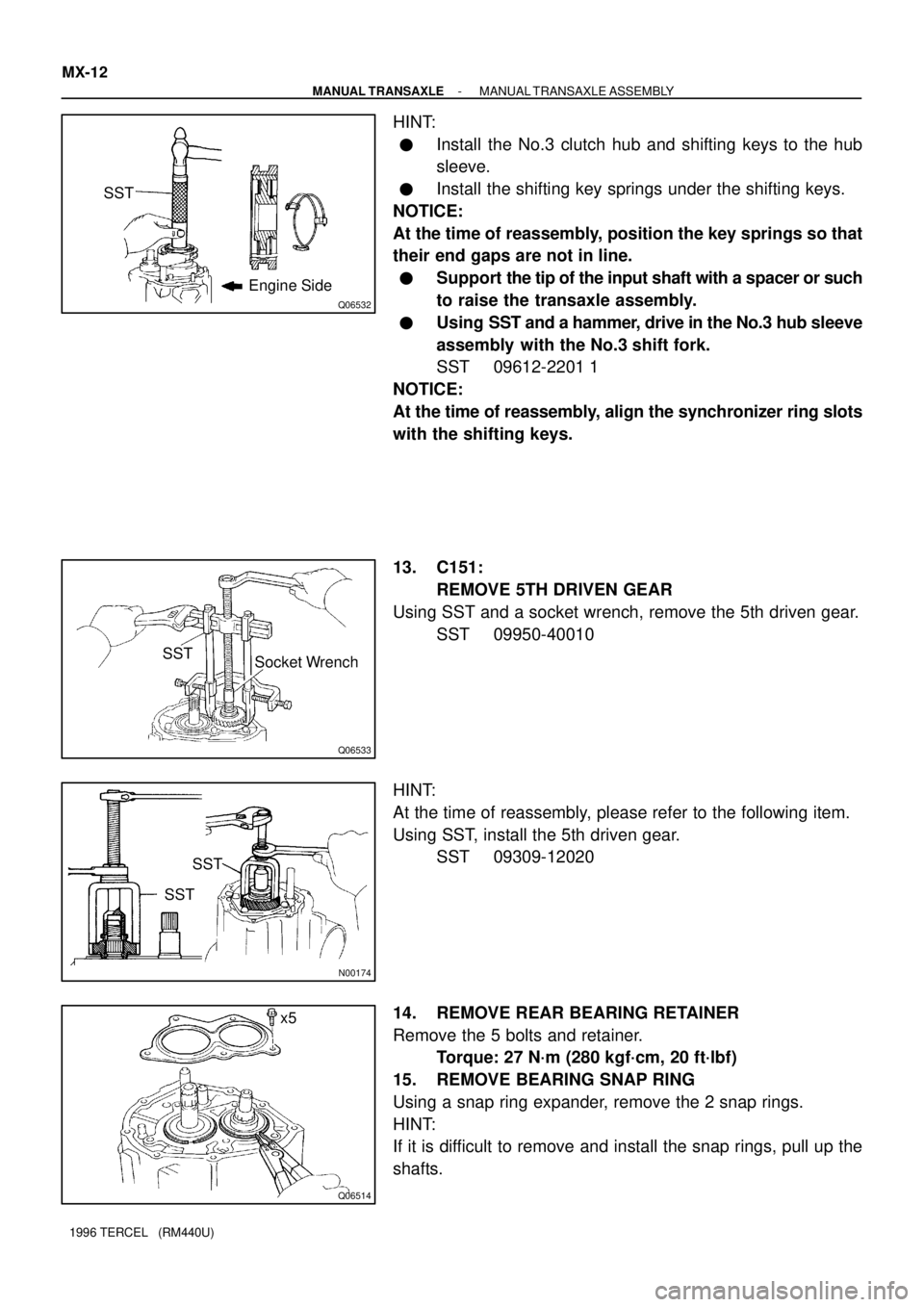
HINT:
�Install the No.3 clutch hub and shifting keys to the hub
sleeve.
�Install the shifting key springs under the shifting keys.
NOTICE:
At the time of reassembly, position the key springs so that
their end gaps are not in line.
�Support the tip of the input shaft with a spacer or such
to raise the transaxle assembly.
�Using SST and a hammer, drive in the No.3 hub sleeve
assembly with the No.3 shift fork.
SST 09612-2201 1
NOTICE:
At the time of reassembly, align the synchronizer ring slots
with the shifting keys.
13. C151:
REMOVE 5TH DRIVEN GEAR
Using SST and a socket wrench, remove the 5th driven gear.
SST 09950-40010
HINT:
At the time of reassembly, please refer to the following item.
Using SST, install the 5th driven gear.
SST 09309-12020
14. REMOVE REAR BEARING RETAINER
Remove the 5 bolts and retainer.
Torque: 27 N´m (280 kgf´cm, 20 ft´lbf)
15. REMOVE BEARING SNAP RING
Using a snap ring expander, remove the 2 snap rings.
HINT:
If it is difficult to remove and install the snap rings, pull up the
shafts.