Page 464 of 1202
EM0K2-04
Z14084
Protrusion
47.5 - 48.5 mm
Mark
EM9934
Adhesive
P20370
Protrusion
EM9938
EM-42
- ENGINE MECHANICALCYLINDER HEAD
1996 TERCEL (RM440U)
REASSEMBLY
HINT:
�Thoroughly clean all parts to be assembled.
�Before installing the parts, apply new engine oil to all slid-
ing and rotating surfaces.
�Replace all gaskets and oil seals with new ones.
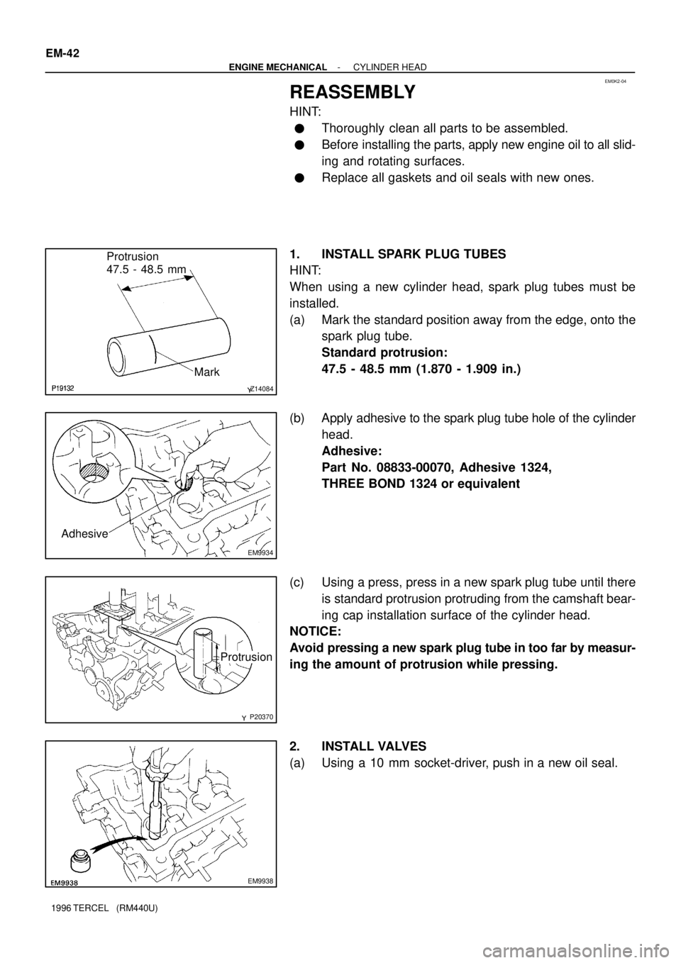
1. INSTALL SPARK PLUG TUBES
HINT:
When using a new cylinder head, spark plug tubes must be
installed.
(a) Mark the standard position away from the edge, onto the
spark plug tube.
Standard protrusion:
47.5 - 48.5 mm (1.870 - 1.909 in.)
(b) Apply adhesive to the spark plug tube hole of the cylinder
head.
Adhesive:
Part No. 08833-00070, Adhesive 1324,
THREE BOND 1324 or equivalent
(c) Using a press, press in a new spark plug tube until there
is standard protrusion protruding from the camshaft bear-
ing cap installation surface of the cylinder head.
NOTICE:
Avoid pressing a new spark plug tube in too far by measur-
ing the amount of protrusion while pressing.
2. INSTALL VALVES
(a) Using a 10 mm socket-driver, push in a new oil seal.
Page 468 of 1202
EG0010
Timing Mark
P20369
Timing Mark
EXIN
Other Timing Mark
P20377
8
6
13 4
2
57
P20248
Seal Packing EM-46
- ENGINE MECHANICALCYLINDER HEAD
1996 TERCEL (RM440U)
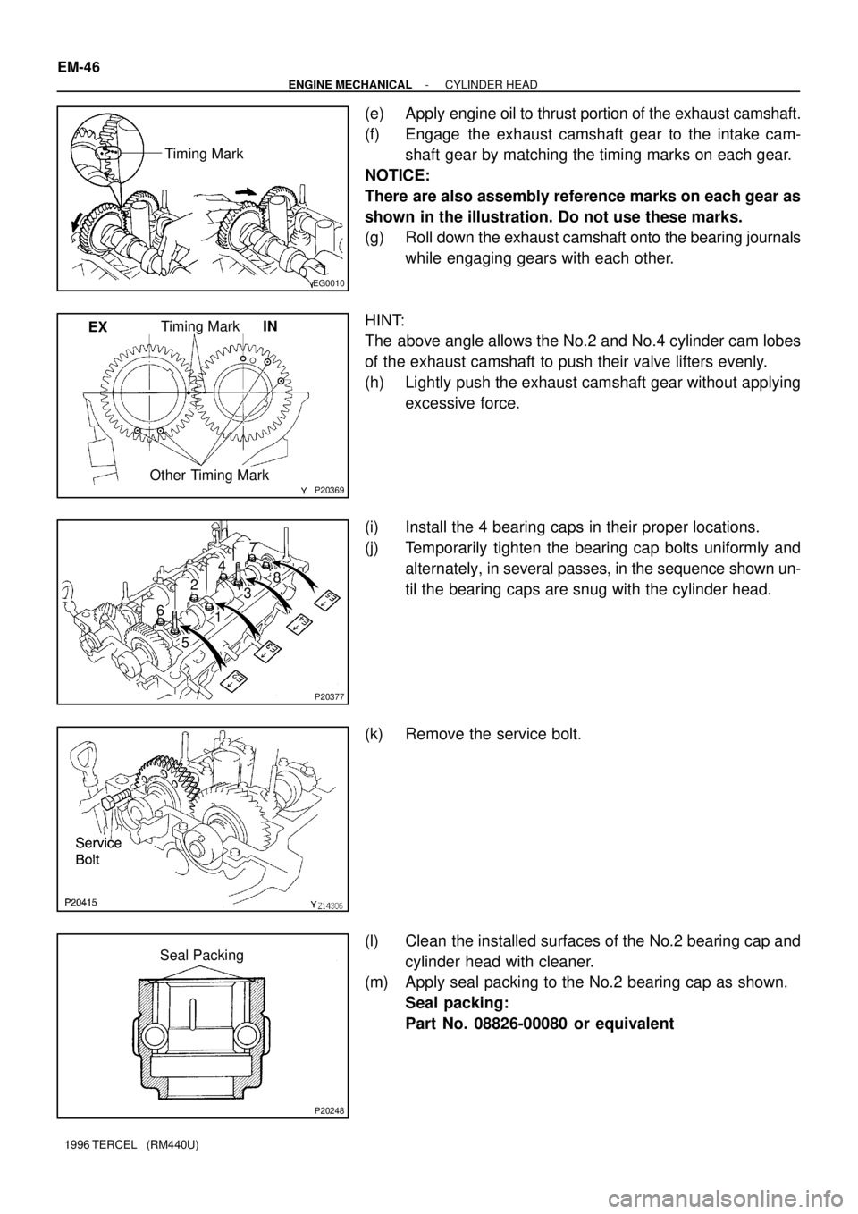
(e) Apply engine oil to thrust portion of the exhaust camshaft.
(f) Engage the exhaust camshaft gear to the intake cam-
shaft gear by matching the timing marks on each gear.
NOTICE:
There are also assembly reference marks on each gear as
shown in the illustration. Do not use these marks.
(g) Roll down the exhaust camshaft onto the bearing journals
while engaging gears with each other.
HINT:
The above angle allows the No.2 and No.4 cylinder cam lobes
of the exhaust camshaft to push their valve lifters evenly.
(h) Lightly push the exhaust camshaft gear without applying
excessive force.
(i) Install the 4 bearing caps in their proper locations.
(j) Temporarily tighten the bearing cap bolts uniformly and
alternately, in several passes, in the sequence shown un-
til the bearing caps are snug with the cylinder head.
(k) Remove the service bolt.
(l) Clean the installed surfaces of the No.2 bearing cap and
cylinder head with cleaner.
(m) Apply seal packing to the No.2 bearing cap as shown.
Seal packing:
Part No. 08826-00080 or equivalent
Page 475 of 1202
EG0023
P20290
- ENGINE MECHANICALCYLINDER HEAD
EM-53
1996 TERCEL (RM440U)
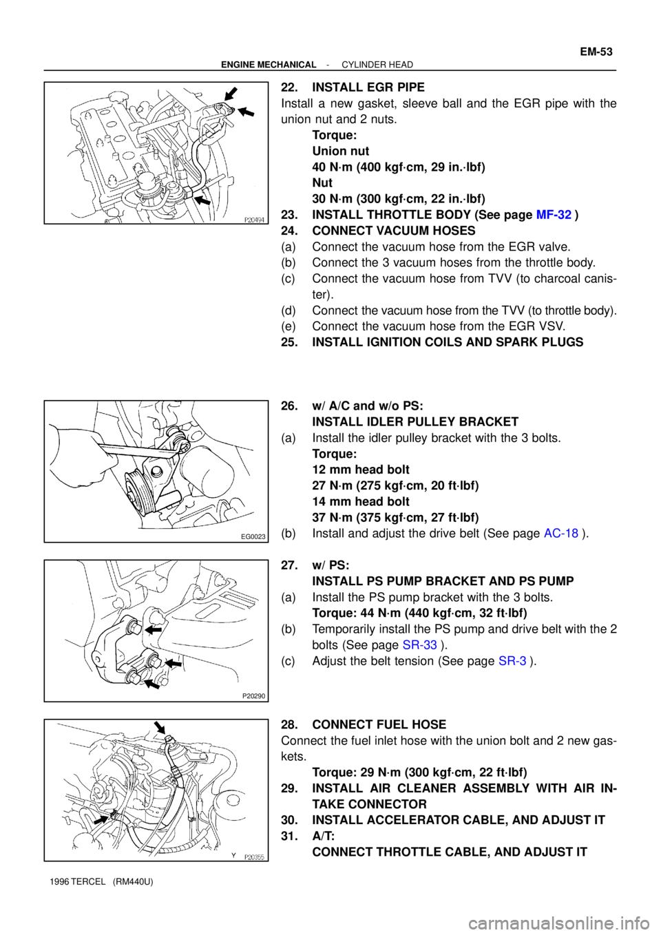
22. INSTALL EGR PIPE
Install a new gasket, sleeve ball and the EGR pipe with the
union nut and 2 nuts.
Torque:
Union nut
40 N´m (400 kgf´cm, 29 in.´lbf)
Nut
30 N´m (300 kgf´cm, 22 in.´lbf)
23. INSTALL THROTTLE BODY (See page MF-32)
24. CONNECT VACUUM HOSES
(a) Connect the vacuum hose from the EGR valve.
(b) Connect the 3 vacuum hoses from the throttle body.
(c) Connect the vacuum hose from TVV (to charcoal canis-
ter).
(d) Connect the vacuum hose from the TVV (to throttle body).
(e) Connect the vacuum hose from the EGR VSV.
25. INSTALL IGNITION COILS AND SPARK PLUGS
26. w/ A/C and w/o PS:
INSTALL IDLER PULLEY BRACKET
(a) Install the idler pulley bracket with the 3 bolts.
Torque:
12 mm head bolt
27 N´m (275 kgf´cm, 20 ft´lbf)
14 mm head bolt
37 N´m (375 kgf´cm, 27 ft´lbf)
(b) Install and adjust the drive belt (See page AC-18).
27. w/ PS:
INSTALL PS PUMP BRACKET AND PS PUMP
(a) Install the PS pump bracket with the 3 bolts.
Torque: 44 N´m (440 kgf´cm, 32 ft´lbf)
(b) Temporarily install the PS pump and drive belt with the 2
bolts (See page SR-33).
(c) Adjust the belt tension (See page SR-3).
28. CONNECT FUEL HOSE
Connect the fuel inlet hose with the union bolt and 2 new gas-
kets.
Torque: 29 N´m (300 kgf´cm, 22 ft´lbf)
29. INSTALL AIR CLEANER ASSEMBLY WITH AIR IN-
TAKE CONNECTOR
30. INSTALL ACCELERATOR CABLE, AND ADJUST IT
31. A/T:
CONNECT THROTTLE CABLE, AND ADJUST IT
Page 479 of 1202
EM1OH-01
- ENGINE MECHANICALENGINE UNIT
EM-57
1996 TERCEL (RM440U)
REMOVAL
1. REMOVE BATTERY
2. REMOVE HOOD
3. REMOVE ENGINE UNDER COVERS
4. DRAIN ENGINE COOLANT
5. DRAIN TRANSAXLE OIL (FLUID)
6. REMOVE AIR CLEANER ASSEMBLY WITH AIR IN-
TAKE CONNECTOR
7. REMOVE RADIATOR (See page CO-16)
8. DISCONNECT ACCELERATOR CABLE
9. DISCONNECT FUEL HOSE
Remove the union bolt and gaskets, and disconnect the fuel in-
let hose.
NOTICE:
Catch leaking fuel in a container.
10. REMOVE CHARCOAL CANISTER
(a) Disconnect the canister hoses.
(b) Remove the charcoal canister.
11. DISCONNECT HOSES
(a) Disconnect the brake booster vacuum hose.
(b) Disconnect the MAP sensor hose.
(c) Disconnect the heater hoses.
12. DISCONNECT SPEEDOMETER CABLE FROM
TRANSAXLE
13. w/ PS:
DISCONNECT IDLE-UP AIR HOSES FROM AIR CON-
TROL VALVE
14. DISCONNECT ENGINE WIRE HARNESS
Disconnect these connectors and wires:
�Main heated oxygen sensor connector
�Oil pressure switch connector
Page 484 of 1202
EM1OI-01
P20245
A/T only
P20161
P20167
P20256
Lower EM-62
- ENGINE MECHANICALENGINE UNIT
1996 TERCEL (RM440U)
INSTALLATION
1. ASSEMBLE ENGINE AND TRANSAXLE
M/T: (See page MX-4)
A132L A/T: (See page AX-26)
A242L A/T: (See page AX-30)
2. INSTALL STARTER
(See page ST-14 and ST-30)
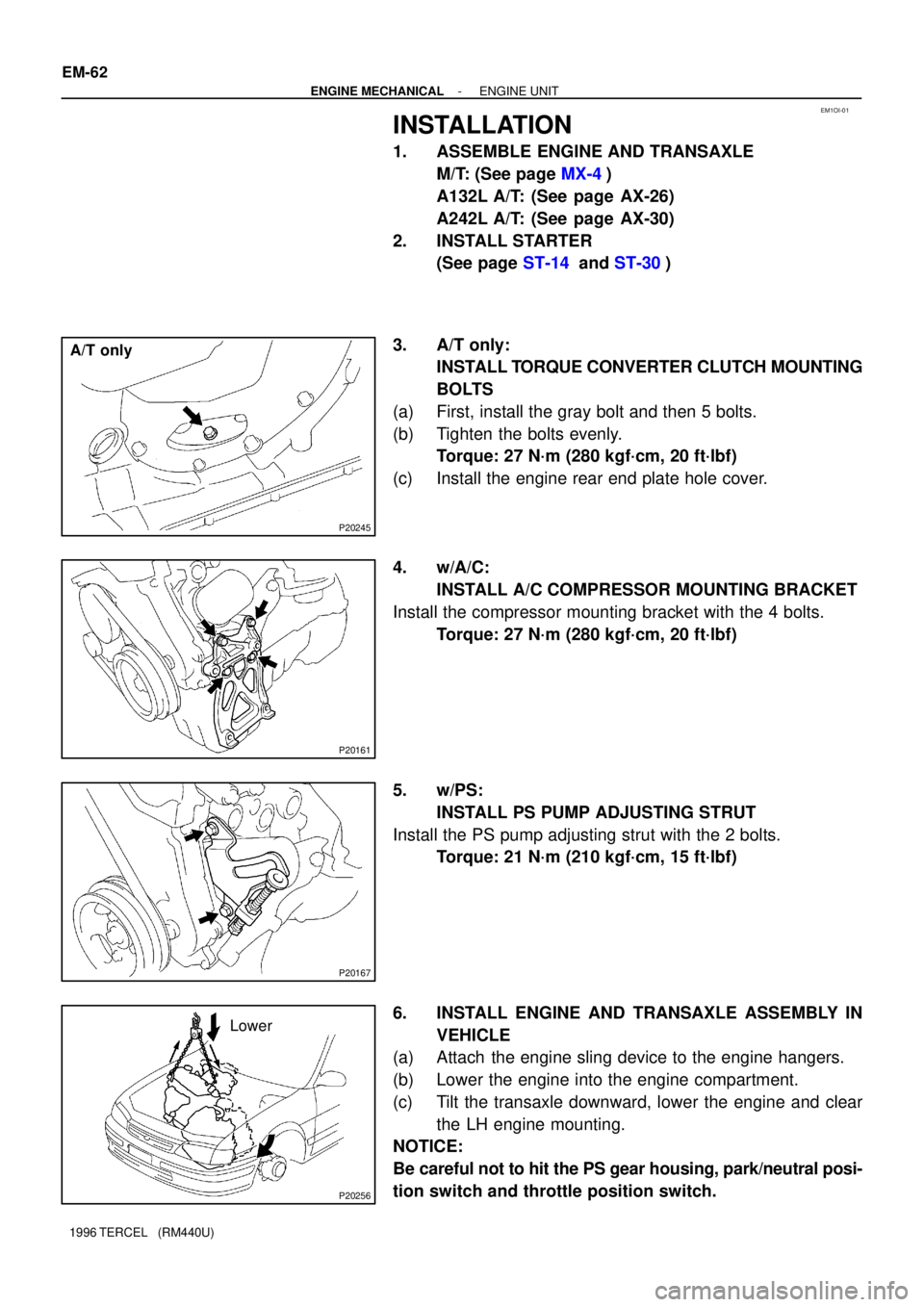
3. A/T only:
INSTALL TORQUE CONVERTER CLUTCH MOUNTING
BOLTS
(a) First, install the gray bolt and then 5 bolts.
(b) Tighten the bolts evenly.
Torque: 27 N´m (280 kgf´cm, 20 ft´lbf)
(c) Install the engine rear end plate hole cover.
4. w/A/C:
INSTALL A/C COMPRESSOR MOUNTING BRACKET
Install the compressor mounting bracket with the 4 bolts.
Torque: 27 N´m (280 kgf´cm, 20 ft´lbf)
5. w/PS:
INSTALL PS PUMP ADJUSTING STRUT
Install the PS pump adjusting strut with the 2 bolts.
Torque: 21 N´m (210 kgf´cm, 15 ft´lbf)
6. INSTALL ENGINE AND TRANSAXLE ASSEMBLY IN
VEHICLE
(a) Attach the engine sling device to the engine hangers.
(b) Lower the engine into the engine compartment.
(c) Tilt the transaxle downward, lower the engine and clear
the LH engine mounting.
NOTICE:
Be careful not to hit the PS gear housing, park/neutral posi-
tion switch and throttle position switch.
Page 489 of 1202
- ENGINE MECHANICALENGINE UNIT
EM-67
1996 TERCEL (RM440U)
19. INSTALL CHARCOAL CANISTER
(a) Install the charcoal canister to the bracket.
(b) Connect the canister hoses.
20. CONNECT FUEL HOSE
Connect the fuel inlet hose with the union bolt and 2 new gas-
kets.
Torque: 29 N´m (300 kgf´cm, 22 ft´lbf)
21. CONNECT ACCELERATOR CABLE, AND ADJUST IT
22. INSTALL RADIATOR (See page CO-22)
23. INSTALL AIR CLEANER ASSEMBLY WITH AIR IN-
TAKE CONNECTOR
24. FILL WITH TRANSAXLE OIL (FLUID)
25. FILL WITH ENGINE COOLANT
26. INSTALL ENGINE UNDER COVERS
27. INSTALL HOOD
28. START ENGINE AND CHECK FOR LEAKS
29. PERFORM ENGINE ADJUSTMENT
30. PERFORM ROAD TEST
Check for abnormal noise, shock, slippage, correct shift points
and smooth operation.
31. RECHECK ENGINE COOLANT AND ENGINE OIL LEV-
ELS
Page 492 of 1202
EM0JQ-06
EM9411
EM9412
P20480
SST
P20478
SST
P20477
12 mm
Hexagon
Wrench EM-70
- ENGINE MECHANICALCYLINDER BLOCK
1996 TERCEL (RM440U)
DISASSEMBLY
1. M/T:
REMOVE CLUTCH COVER AND DISC
2. REMOVE FLYWHEEL (M/T) OR DRIVE PLATE (A/T)
3. REMOVE REAR END PLATE
4. INSTALL ENGINE TO ENGINE STAND FOR DIS-
ASSEMBLY
5. REMOVE TIMING BELT AND PULLEYS
6. REMOVE CYLINDER HEAD
7. REMOVE OIL DIPSTICK GUIDE AND GENERATOR
ADJUSTING BAR
8. REMOVE WATER PUMP WITH WATER INLET PIPE
9. REMOVE GENERATOR BRACKET
10. REMOVE KNOCK SENSOR
Using SST, remove the knock sensor.
SST 09816-30010
11. REMOVE RH ENGINE MOUNTING BRACKET
12. REMOVE OIL FILTER
13. REMOVE OIL PRESSURE SWITCH
Using SST, remove the oil pressure switch.
SST 09816-30010
14. REMOVE OIL PUMP AND PRESSURE REGULATOR
VA LV E
15. REMOVE OIL FILTER UNION
Using a 12 mm hexagon wrench, remove the oil filter union.
Page 493 of 1202
EM9988
EM3441
P20487
EM9392
EM3444
- ENGINE MECHANICALCYLINDER BLOCK
EM-71
1996 TERCEL (RM440U)
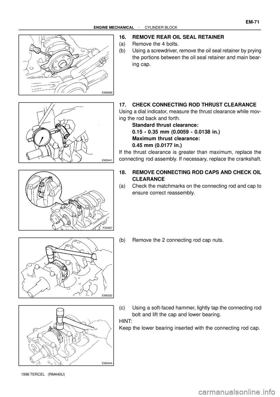
16. REMOVE REAR OIL SEAL RETAINER
(a) Remove the 4 bolts.
(b) Using a screwdriver, remove the oil seal retainer by prying
the portions between the oil seal retainer and main bear-
ing cap.
17. CHECK CONNECTING ROD THRUST CLEARANCE
Using a dial indicator, measure the thrust clearance while mov-
ing the rod back and forth.
Standard thrust clearance:
0.15 - 0.35 mm (0.0059 - 0.0138 in.)
Maximum thrust clearance:
0.45 mm (0.0177 in.)
If the thrust clearance is greater than maximum, replace the
connecting rod assembly. If necessary, replace the crankshaft.
18. REMOVE CONNECTING ROD CAPS AND CHECK OIL
CLEARANCE
(a) Check the matchmarks on the connecting rod and cap to
ensure correct reassembly.
(b) Remove the 2 connecting rod cap nuts.
(c) Using a soft-faced hammer, lightly tap the connecting rod
bolt and lift the cap and lower bearing.
HINT:
Keep the lower bearing inserted with the connecting rod cap.