Page 738 of 1202

MX07O-02
D02999
Engine Side
Z08629
N00067
N00068
- MANUAL TRANSAXLEINPUT SHAFT
MX-25
1996 TERCEL (RM440U)
REASSEMBLY
HINT:
Coat all of the sliding and rotating surfaces with gear oil before
reassembly.
1. INSTALL NO.2 CLUTCH HUB INTO HUB SLEEVE
(a) Install the clutch hub and shifting keys to the hub sleeve.
(b) Install the shifting key springs under the shifting keys.
NOTICE:
Position the key springs so that their end gaps are not in
line.
2. INSTALL 3RD GEAR, NEEDLE ROLLER BEARING,
SYNCHRONIZER RING AND NO.2 HUB SLEEVE AS-
SEMBLY TO INPUT SHAFT
(a) Apply gear oil to the needle roller bearings.
(b) Place the synchronizer ring on the gear and align the ring
slots with the shifting keys.
(c) Using a press, install the 3rd gear and No.2 hub sleeve
assembly.
3. INSTALL SNAP RING
(a) Select a snap ring that allows the minimum axial play.
MarkThickness mm (in.)MarkThickness mm (in.)
02.30 (0.0906)32.48 (0.0976)
12.36 (0.0929)42.54 (0.1000)
22.42 (0.0953)52.60 (0.1024)
(b) Using a screwdriver and hammer, install the snap ring.
4. INSPECT 3RD GEAR THRUST CLEARANCE
(See page MX-21)
Page 745 of 1202
MX07S-03
CM0009
Engine Side
N00077
N00078
N00079
MX-32
- MANUAL TRANSAXLEOUTPUT SHAFT
1996 TERCEL (RM440U)
REASSEMBLY
HINT:
Coat all of the sliding and rotating surfaces with gear oil before
assembly.
1. INSTALL NO.1 CLUTCH HUB INTO HUB SLEEVE
(a) Install the No.1 clutch hub and shifting keys to the No.1
hub sleeve.
(b) Install the shifting key springs under the shifting keys.
NOTICE:
Position the key springs so that their end gaps are not in
line.
2. INSTALL BALL, THRUST WASHER, 1ST GEAR,
NEEDLE ROLLER BEARING, SYNCHRONIZER RING
AND NO.1 HUB SLEEVE ASSEMBLY TO OUTPUT
SHAFT
(a) Install the ball to the shaft.
(b) Fit the thrust washer groove securely over the locking ball
when installing the thrust on the shaft.
(c) Apply gear oil to the needle roller bearing.
(d) Place the synchronizer ring on the gear and align the ring
slots with the shifting keys.
(e) Using a press, install the 1st gear and No.1 hub sleeve.
Page 778 of 1202
AX08M-03
Q07634
RH Drive Shaft
� Snap
RingSpeedometer
Cable
Rear Engine
Mounting InsulatorAir Cleaner
Assembly
� Snap RingTie Rod End
LH Drive Shaft
Nut Cap Plug for Governor Pressure Test
Oxygen Sensor
Front Exhaust Pipe Torque Converter
Clutch
Clip
Control Cable
� Gasket
Compression Spring
Engine Under Cover� Cotter Pin Starter
� Gasket
Clamp x 6
Plug for Line
Pressure Test
� Non-reusable partx 5
Converter
Cover
- AUTOMATIC TRANSAXLE (A132L)AUTOMATIC TRANSAXLE UNIT
AX-25
777 Author�: Date�:
1996 TERCEL (RM440U)
AUTOMATIC TRANSAXLE UNIT
COMPONENTS
Page 779 of 1202

AX08N-03
Q06547
Q06548
Q07635
Q08079
AX-26
- AUTOMATIC TRANSAXLE (A132L)AUTOMATIC TRANSAXLE UNIT
1996 TERCEL (RM440U)
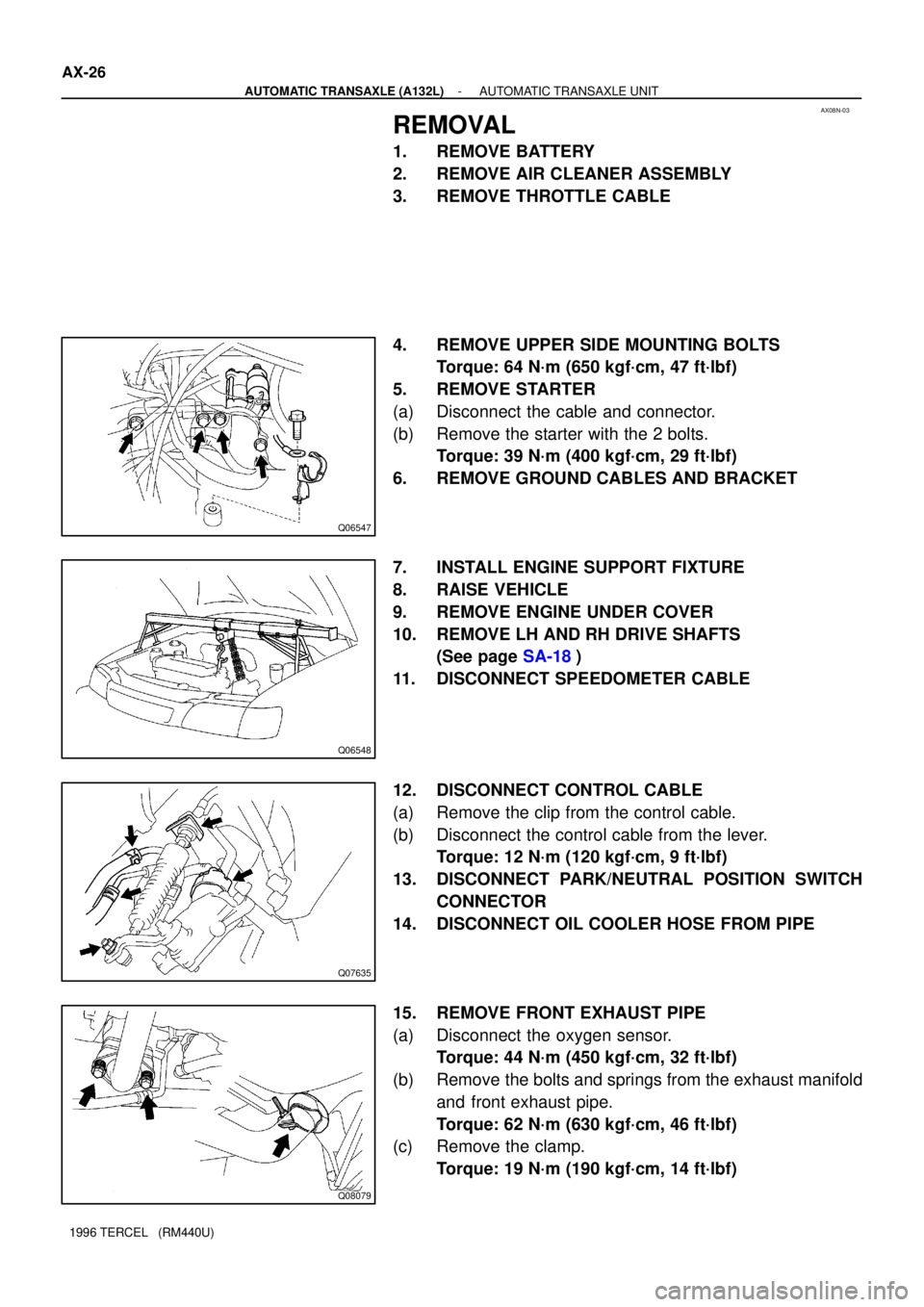
REMOVAL
1. REMOVE BATTERY
2. REMOVE AIR CLEANER ASSEMBLY
3. REMOVE THROTTLE CABLE
4. REMOVE UPPER SIDE MOUNTING BOLTS
Torque: 64 N´m (650 kgf´cm, 47 ft´lbf)
5. REMOVE STARTER
(a) Disconnect the cable and connector.
(b) Remove the starter with the 2 bolts.
Torque: 39 N´m (400 kgf´cm, 29 ft´lbf)
6. REMOVE GROUND CABLES AND BRACKET
7. INSTALL ENGINE SUPPORT FIXTURE
8. RAISE VEHICLE
9. REMOVE ENGINE UNDER COVER
10. REMOVE LH AND RH DRIVE SHAFTS
(See page SA-18)
11. DISCONNECT SPEEDOMETER CABLE
12. DISCONNECT CONTROL CABLE
(a) Remove the clip from the control cable.
(b) Disconnect the control cable from the lever.
Torque: 12 N´m (120 kgf´cm, 9 ft´lbf)
13. DISCONNECT PARK/NEUTRAL POSITION SWITCH
CONNECTOR
14. DISCONNECT OIL COOLER HOSE FROM PIPE
15. REMOVE FRONT EXHAUST PIPE
(a) Disconnect the oxygen sensor.
Torque: 44 N´m (450 kgf´cm, 32 ft´lbf)
(b) Remove the bolts and springs from the exhaust manifold
and front exhaust pipe.
Torque: 62 N´m (630 kgf´cm, 46 ft´lbf)
(c) Remove the clamp.
Torque: 19 N´m (190 kgf´cm, 14 ft´lbf)
Page 812 of 1202
AX086-04
Q07636
RH Drive ShaftStarterAir Cleaner
Assembly
Speedometer Cable
Rear Engine Mounting Insulator
Plug for Governor
Pressure Test
Tie Rod End
� Snap Ring
LH Drive Shaft
� Gasket
Clamp
Nut Cap
� Cotter Pin O/D Solenoid
Connector � Snap
Ring
x6
Hole Plug
Torque Converter
Clutch
Clip
Control
Cable
Plug for Line Pressure Test
Oxygen Sensor
� Gasket
Front Exhaust Pipe
Compression Spring
Engine Under Cover
� Non-reusable part
- AUTOMATIC TRANSAXLE (A242L)AUTOMATIC TRANSAXLE UNIT
AX-29
811 Author�: Date�:
1996 TERCEL (RM440U)
AUTOMATIC TRANSAXLE UNIT
COMPONENTS
Page 813 of 1202

AX087-03
Q06569
Q06548
Q06571
Q06572
AX-30
- AUTOMATIC TRANSAXLE (A242L)AUTOMATIC TRANSAXLE UNIT
1996 TERCEL (RM440U)
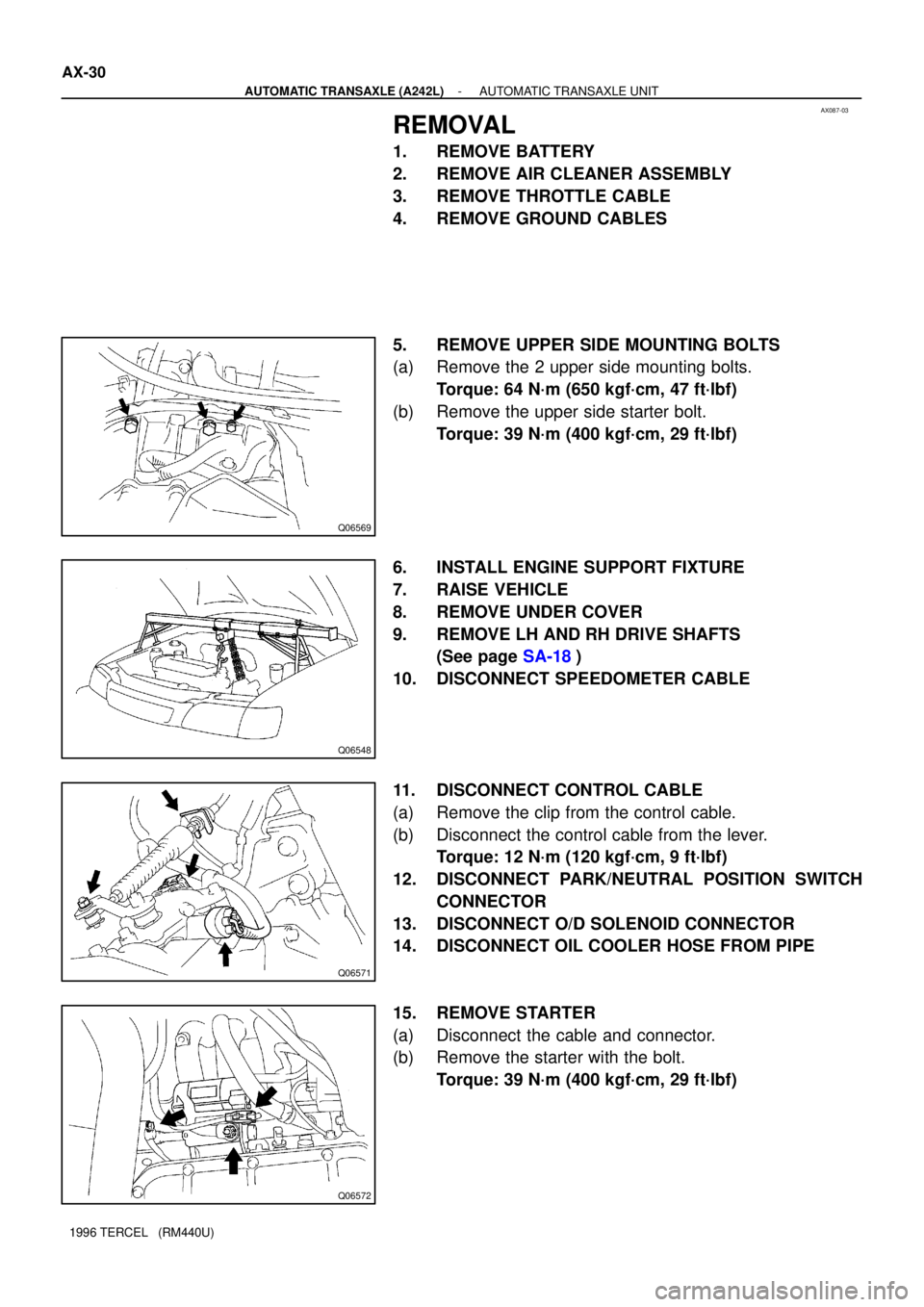
REMOVAL
1. REMOVE BATTERY
2. REMOVE AIR CLEANER ASSEMBLY
3. REMOVE THROTTLE CABLE
4. REMOVE GROUND CABLES
5. REMOVE UPPER SIDE MOUNTING BOLTS
(a) Remove the 2 upper side mounting bolts.
Torque: 64 N´m (650 kgf´cm, 47 ft´lbf)
(b) Remove the upper side starter bolt.
Torque: 39 N´m (400 kgf´cm, 29 ft´lbf)
6. INSTALL ENGINE SUPPORT FIXTURE
7. RAISE VEHICLE
8. REMOVE UNDER COVER
9. REMOVE LH AND RH DRIVE SHAFTS
(See page SA-18)
10. DISCONNECT SPEEDOMETER CABLE
11. DISCONNECT CONTROL CABLE
(a) Remove the clip from the control cable.
(b) Disconnect the control cable from the lever.
Torque: 12 N´m (120 kgf´cm, 9 ft´lbf)
12. DISCONNECT PARK/NEUTRAL POSITION SWITCH
CONNECTOR
13. DISCONNECT O/D SOLENOID CONNECTOR
14. DISCONNECT OIL COOLER HOSE FROM PIPE
15. REMOVE STARTER
(a) Disconnect the cable and connector.
(b) Remove the starter with the bolt.
Torque: 39 N´m (400 kgf´cm, 29 ft´lbf)
Page 868 of 1202
BR2237
BR0RJ-01
BR2238
GOOD NO GOOD
1st2nd3rd
- BRAKEBRAKE BOOSTER ASSEMBLY
BR-15
889 Author�: Date�:
1996 TERCEL (RM440U)
BRAKE BOOSTER ASSEMBLY
ON-VEHICLE INSPECTION
1. OPERATING CHECK
(a) Depress the brake pedal several times with the engine off
and check that there is no change in the pedal reserve
distance.
(b) Depress the brake pedal and start the engine. If the pedal
goes down slightly, operation is normal.
2. AIR TIGHTNESS CHECK
(a) Start the engine and stop it after 1 or 2 minutes. Depress
the brake pedal several times slowly.
If the pedal goes down farthest the 1st time, but gradually rises
after the 2nd or 3rd time, the booster is air tight.
(b) Depress the brake pedal while the engine is running, and
stop the engine with the pedal depressed. If there is no
change in the pedal reserve travel after holding the pedal
for 30 seconds, the booster is air tight.
Page 948 of 1202

SR0KY-02
R11074
SST
SR4244
- STEERINGPOWER STEERING GEAR
SR-49
1996 TERCEL (RM440U)
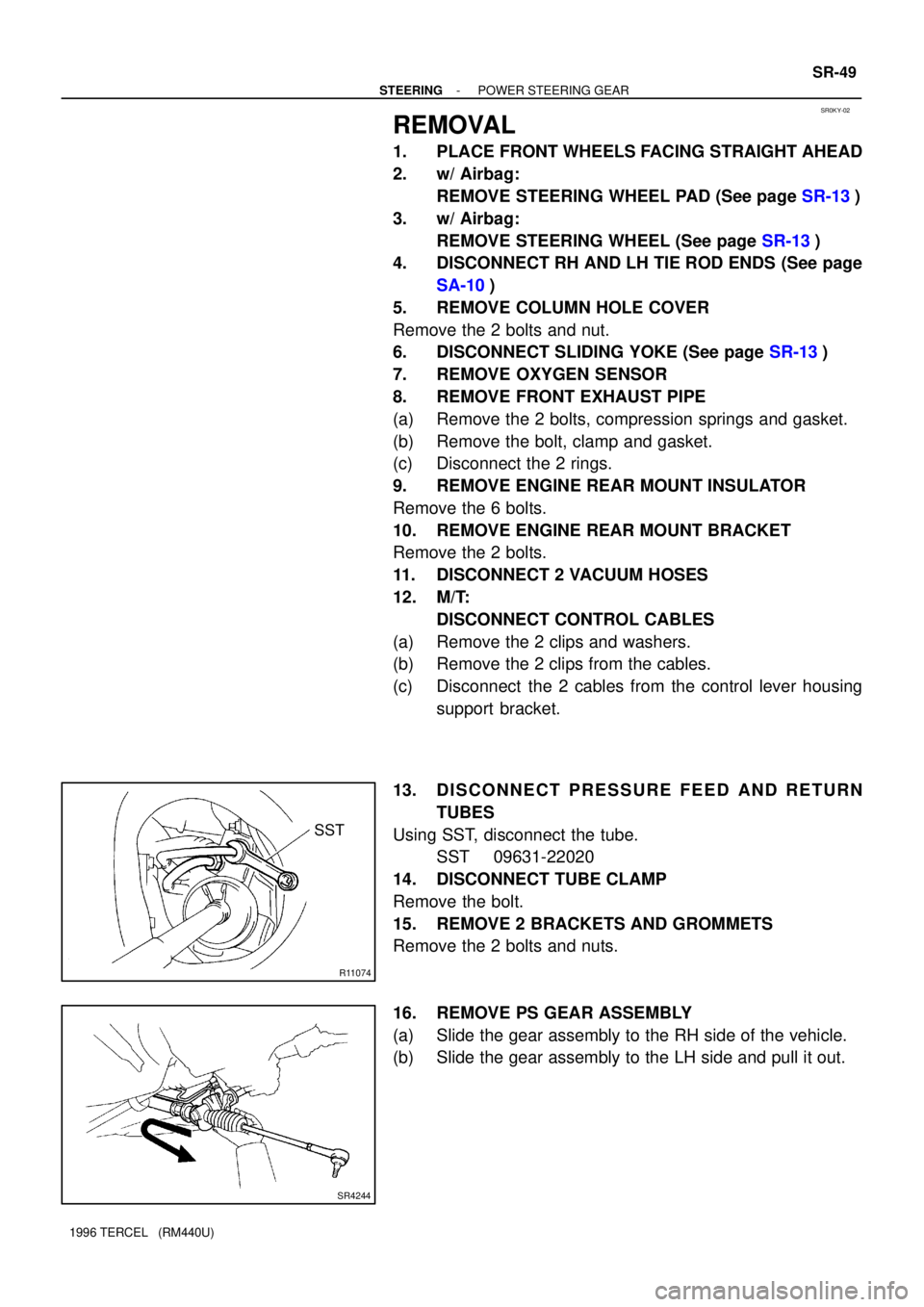
REMOVAL
1. PLACE FRONT WHEELS FACING STRAIGHT AHEAD
2. w/ Airbag:
REMOVE STEERING WHEEL PAD (See page SR-13)
3. w/ Airbag:
REMOVE STEERING WHEEL (See page SR-13)
4. DISCONNECT RH AND LH TIE ROD ENDS (See page
SA-10)
5. REMOVE COLUMN HOLE COVER
Remove the 2 bolts and nut.
6. DISCONNECT SLIDING YOKE (See page SR-13)
7. REMOVE OXYGEN SENSOR
8. REMOVE FRONT EXHAUST PIPE
(a) Remove the 2 bolts, compression springs and gasket.
(b) Remove the bolt, clamp and gasket.
(c) Disconnect the 2 rings.
9. REMOVE ENGINE REAR MOUNT INSULATOR
Remove the 6 bolts.
10. REMOVE ENGINE REAR MOUNT BRACKET
Remove the 2 bolts.
11. DISCONNECT 2 VACUUM HOSES
12. M/T:
DISCONNECT CONTROL CABLES
(a) Remove the 2 clips and washers.
(b) Remove the 2 clips from the cables.
(c) Disconnect the 2 cables from the control lever housing
support bracket.
13. DISCONNECT PRESSURE FEED AND RETURN
TUBES
Using SST, disconnect the tube.
SST 09631-22020
14. DISCONNECT TUBE CLAMP
Remove the bolt.
15. REMOVE 2 BRACKETS AND GROMMETS
Remove the 2 bolts and nuts.
16. REMOVE PS GEAR ASSEMBLY
(a) Slide the gear assembly to the RH side of the vehicle.
(b) Slide the gear assembly to the LH side and pull it out.