Page 288 of 1202

R13006
DLC1
E
1
TcTs
BR3904
0.13 sec. 0.13 sec.
ON
OFF
BR3893
Malfunction Code (Example Code 72, 76)
72 67
ON
OFF
0.5 sec. 0.5 sec. 0.5 sec. 0.5 sec.1.5 sec.
2.5 sec.4 sec.
Repeat
- DIAGNOSTICSANTI-LOCK BRAKE SYSTEM
DI-1 13
1996 TERCEL (RM440U)
2. SPEED SENSOR SIGNAL CHECK
(a) Check the speed sensor signal.
(1) Turn the ignition switch OFF.
(2) Using SST, connect terminals Ts and E
1 of the
DLC1.
SST 09843-18020
(3) Start the engine.
(4) Check that the ABS warning light blinks.
HINT:
If the ABS warning light does not blink, inspect the ABS warning
light circuit (See page DI-138).
(5) Drive the vehicle faster than 45 km/h (28 mph) for
several seconds.
(6) Stop the vehicle.
(7) Using SST, connect terminals Tc and E
1 of the
DLC1.
SST 09843-18020
(8) Read the number of blinks of the ABS warning light.
HINT:
See the list of DTCs shown on the next page.
�If every sensor is normal, a normal code is output (A cycle
of 0.25 sec. ON and 0.25 sec. OFF is repeated).
�If 2 or more malfunctions are indicated at the same time,
the lowest numbered code will be displayed 1st.
(9) After doing the check, disconnect terminals Ts and
E
1, and Tc and E1 of the DLC1, and turn ignition
switch OFF.
Page 290 of 1202

DI4LQ-02
- DIAGNOSTICSANTI-LOCK BRAKE SYSTEM
DI-1 15
1996 TERCEL (RM440U)
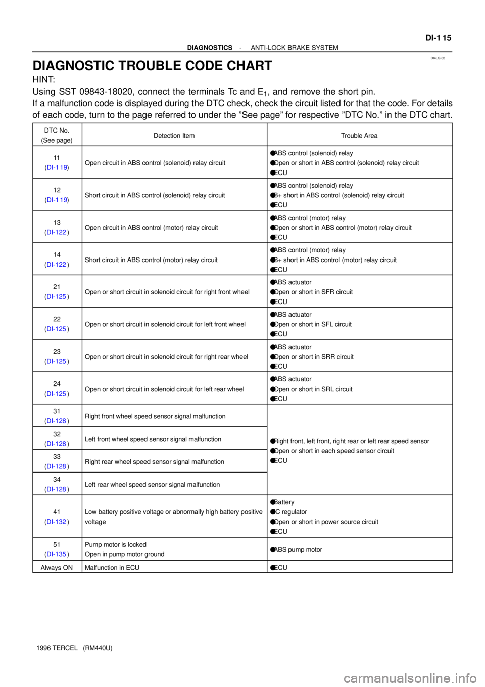
DIAGNOSTIC TROUBLE CODE CHART
HINT:
Using SST 09843-18020, connect the terminals Tc and E
1, and remove the short pin.
If a malfunction code is displayed during the DTC check, check the circuit listed for that the code. For details
of each code, turn to the page referred to under the ºSee pageº for respective ºDTC No.º in the DTC chart.
DTC No.
(See page)Detection ItemTrouble Area
11
(DI-1 19)Open circuit in ABS control (solenoid) relay circuit
�ABS control (solenoid) relay
�Open or short in ABS control (solenoid) relay circuit
�ECU
12
(DI-1 19)Short circuit in ABS control (solenoid) relay circuit
�ABS control (solenoid) relay
�B+ short in ABS control (solenoid) relay circuit
�ECU
13
(DI-122)Open circuit in ABS control (motor) relay circuit
�ABS control (motor) relay
�Open or short in ABS control (motor) relay circuit
�ECU
14
(DI-122)Short circuit in ABS control (motor) relay circuit
�ABS control (motor) relay
�B+ short in ABS control (motor) relay circuit
�ECU
21
(DI-125)Open or short circuit in solenoid circuit for right front wheel
�ABS actuator
�Open or short in SFR circuit
�ECU
22
(DI-125)Open or short circuit in solenoid circuit for left front wheel
�ABS actuator
�Open or short in SFL circuit
�ECU
23
(DI-125)Open or short circuit in solenoid circuit for right rear wheel
�ABS actuator
�Open or short in SRR circuit
�ECU
24
(DI-125)Open or short circuit in solenoid circuit for left rear wheel
�ABS actuator
�Open or short in SRL circuit
�ECU
31
(DI-128)Right front wheel speed sensor signal malfunction
32
(DI-128)Left front wheel speed sensor signal malfunction�Right front, left front, right rear or left rear speed sensor
O htihd iit33
(DI-128)Right rear wheel speed sensor signal malfunction
�Open or short in each speed sensor circuit
�ECU
34
(DI-128)Left rear wheel speed sensor signal malfunction
41
(DI-132)Low battery positive voltage or abnormally high battery positive
voltage
�Battery
�IC regulator
�Open or short in power source circuit
�ECU
51
(DI-135)Pump motor is locked
Open in pump motor ground�ABS pump motor
Always ONMalfunction in ECU�ECU
Page 293 of 1202

DI4LT-02
DI-1 18
- DIAGNOSTICSANTI-LOCK BRAKE SYSTEM
1996 TERCEL (RM440U)
PROBLEM SYMPTOMS TABLE
If a normal code is displayed during the DTC check but the problem still occurs, check the circuits for each
problem symptom in the order given in the table below and proceed to the relevant page for troubleshooting.
SymptomsSuspected AreaSee page
ABS does not operate
Only when 1 - 4 are all normal and the problem is still occurring, replace the ABS
ECU
6. Check the DTC, reconfirming that the normal code is output
7. IG power source circuit
8. Speed sensor circuit
9. Check the ABS actuator with a checker
If abnormal, check the hydraulic circuit for leakage (See page DI-145).
DI-1 11
DI-132
DI-128
BR-35
ABS does not operate effi-
ciently
Only when 1 - 4 are all normal and the problem is still occurring, replace the ABS
ECU
1. Check the DTC, reconfirming that the normal code is output
2. Speed sensor circuit
3. Stop light switch circuit
4. Check the ABS actuator with a checker
If abnormal, check the hydraulic circuit for leakage (See page DI-145)
DI-1 11
DI-128
DI-136
BR-35
ABS warning light abnormal1. ABS warning light circuit
2. ABS ECUDI-138
-
DTC check cannot be done
Only when 1 and 2 are all normal and the problem is still occurring, replace the
ABS ECU
1. ABS warning light circuit
2. Tc terminal circuit
DI-138
DI-141
Speed sensor signal check
cannot be done1. Ts terminal circuit
2. ABS ECUDI-143
-
Page 316 of 1202
R12884
SRS ECU
A1212 V
EA14
Tc
E
1
J/C
A A
DLC111
EC
BR
Tc
325
P-B P-B P-BABS ECU
J1
BR
R13006
TcE1
DLC1
- DIAGNOSTICSANTI-LOCK BRAKE SYSTEM
DI-141
1996 TERCEL (RM440U)
Tc Terminal Circuit
CIRCUIT DESCRIPTION
Connecting between terminals Tc and E1 of the DLC1 cause the ECU to display the DTC by flashing the ABS
warning light.
WIRING DIAGRAM
INSPECTION PROCEDURE
1 Check voltage between terminals Tc and E1 of DLC1.
CHECK:
(a) Turn the ignition switch ON.
(b) Measure the voltage between terminals Tc and E
1 of the
DLC1.
OK:
Voltage: 10 - 14 V
OK If ABS warning light does not blink even after Tc
and E
1 are connected, ECU may be defective.
NG
DI4M0-02
Page 326 of 1202

DI4M7-02
- DIAGNOSTICSSUPPLEMENTAL RESTRAINT SYSTEM
DI-151
1996 TERCEL (RM440U)
DIAGNOSTIC TROUBLE CODE CHART
If a malfunction code is displayed during the DTC check, check the circuit listed for that code in the table
below (Proceed to the page given for that circuit.).
DTC No.
(See Page)Detection ItemTrouble AreaSRS
Warning Light
Nl�System normal-OFFNormal
(DI-177)�Source Voltage drop�Battery
�Airbag sensor assemblyON
11
(DI-155)
�Short in squib circuit (to ground)�Steering wheel pad (D squib)
�Front passenger airbag assembly (P squib)
�Spiral cable
�Airbag sensor assembly
�Wire harness
ON
12
(DI-162)
�Short in squib circuit (to B+)�Steering wheel pad (D squib)
�Front passenger airbag assembly (P squib)
�Spiral cable
�Airbag sensor assembly
�Wire harness
ON
14
(DI-168)
�Open in D squib circuit�Steering wheel pad (D squib)
�Spiral cable
�Airbag sensor assembly
�Wire harness
ON
31
(DI-172)�Airbag sensor assembly malfunction�Airbag sensor assemblyON
54
(DI-174)�Open in P squib circuit�Front passenger airbag assembly (P squib)
�Airbag sensor assembly
�Wire harness
ON
HINT:
�When the SRS warning light remains lit up and the DTC is the normal code, this means a source voltage
drops.
This malfunction is not stored in memory by the airbag sensor assembly and if the power source volt-
age returns to normal, the SRS warning light will automatically go out.
�When 2 or more codes are indicated, the codes will be displayed in numeral order starting from the
lowest numbered code.
�If a code not listed on the chart is displayed, the airbag sensor assembly is faulty.
Page 329 of 1202
DI4MA-01
DI-154
- DIAGNOSTICSSUPPLEMENTAL RESTRAINT SYSTEM
1996 TERCEL (RM440U)
PROBLEM SYMPTOMS TABLE
Proceed with troubleshooting of each circuit in the table below.
SymptomSuspect AreaSee page
�With the ignition switch at ACC or ON, the SRS warning light
sometimes lights up after approx. 6 seconds have elapsed.
�SRS warning light is always lit up even when ignition switch is in
the LOCK position.
�SRS warning light system malfunction
(Always lit up when ignition switch is in LOCK position.)DI-180
�With the ignition switch at ACC or ON, the SRS warning light
does not light up.�SRS warning light system malfunction
(Does not light up, when ignition switch is turned to ACC
or ON.)
DI-182
�DTC not displayed.
�SRS warning light is always lit up a DTC check procedure.
�DTC displayed without Tc and E1 terminal connection.
�Tc terminal circuitDI-185
Page 347 of 1202

R14285 AB0119H00021
Airbag Sensor Assembly ON
IG2 ACC
(+) (-)
DI-172
- DIAGNOSTICSSUPPLEMENTAL RESTRAINT SYSTEM
1996 TERCEL (RM440U)
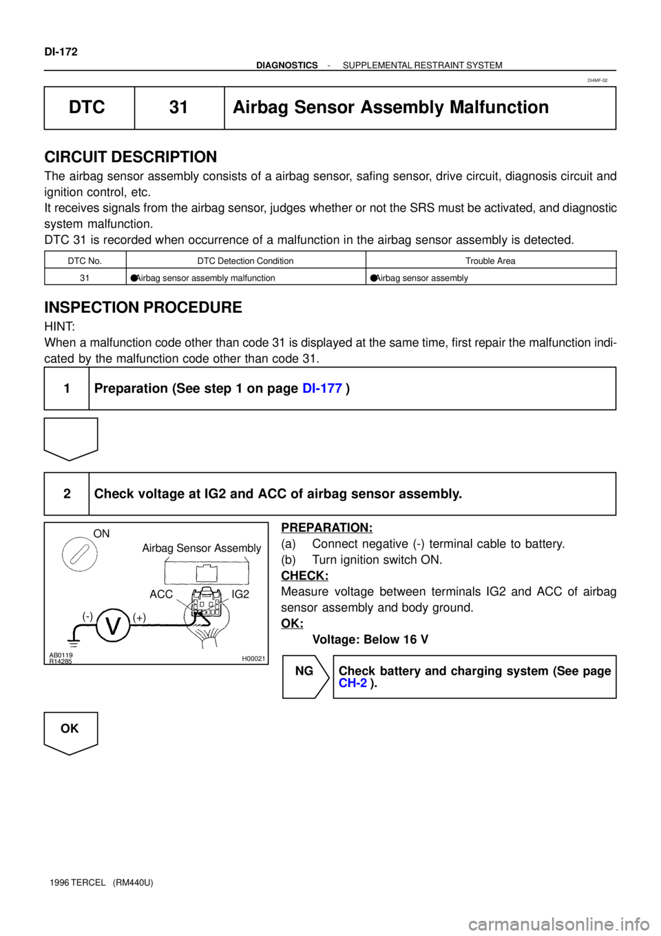
DTC 31 Airbag Sensor Assembly Malfunction
CIRCUIT DESCRIPTION
The airbag sensor assembly consists of a airbag sensor, safing sensor, drive circuit, diagnosis circuit and
ignition control, etc.
It receives signals from the airbag sensor, judges whether or not the SRS must be activated, and diagnostic
system malfunction.
DTC 31 is recorded when occurrence of a malfunction in the airbag sensor assembly is detected.
DTC No.DTC Detection ConditionTrouble Area
31�Airbag sensor assembly malfunction�Airbag sensor assembly
INSPECTION PROCEDURE
HINT:
When a malfunction code other than code 31 is displayed at the same time, first repair the malfunction indi-
cated by the malfunction code other than code 31.
1 Preparation (See step 1 on page DI-177)
2 Check voltage at IG2 and ACC of airbag sensor assembly.
PREPARATION:
(a) Connect negative (-) terminal cable to battery.
(b) Turn ignition switch ON.
CHECK:
Measure voltage between terminals IG2 and ACC of airbag
sensor assembly and body ground.
OK:
Voltage: Below 16 V
NG Check battery and charging system (See page
CH-2).
OK
DI4MF-02
Page 352 of 1202

H09396
MAIN
FL
B
ALT
B-RB-R
2 2
Engine
Room
R/B
AM1
W-GDriver Side J/B
1
1J
1BW-G 2ACC
AM13
B-Y4
1B
1H
CIG/RADIO Driver Side J/B
G-R*1
10
ACCAirbag
Sensor
Assembly
8
*2
B-OIG2 *1
9
7
*2 2
1H 1B5
IGN B-W 6
AM2
Ignition
Switch 7 B-R 12
IC1 B-R
2
AM2
EA2 1
B*1: USA
*2: CANADA EA214
- DIAGNOSTICSSUPPLEMENTAL RESTRAINT SYSTEM
DI-177
1996 TERCEL (RM440U)
DTC Normal Source Voltage Drop
CIRCUIT DESCRIPTION
The SRS is equipped with a voltage-increase circuit (DC-DC converter) in the airbag sensor assembly in
case the source voltage drops.
When the battery voltage drops, the voltage-increase circuit (DC-DC converter) functions to increase the
voltage of the SRS to normal voltage.
The diagnosis system malfunction display for this circuit is different to other circuits-when the SRS warning
light remains lit up and the DTC is a normal code, source voltage drop is indicated.
Malfunction in this circuit is not recorded in the airbag sensor assembly and the source voltage returns to
normal, the SRS warning light automatically goes off.
DTC No.DTC Detection ConditionTrouble Area
(Normal)Source voltage drop.�Battery
�Airbag sensor assembly
WIRING DIAGRAM
DI4MI-02