Page 467 of 1202

P20418
Main Gear
Sub-GearSST
P00400
No.3 Cylinder
No.4 Cylinder
P20378
8
6 13
24
57
- ENGINE MECHANICALCYLINDER HEAD
EM-45
1996 TERCEL (RM440U)
(e) Using snap ring pliers, install the snap ring.
(f) Using SST, align the holes of the camshaft main gear and
sub-gear by turning camshaft sub-gear clockwise, and
install a service bolt.
SST 09960-10010 (09962-01000, 09963-00500)
4. INSTALL INTAKE AND EXHAUST CAMSHAFTS
NOTICE:
Since the thrust clearance of the camshaft is small, the
camshaft must be kept level while it is being installed. If the
camshaft is not kept level, the portion of the cylinder head
receiving the shaft thrust may crack or be damaged, caus-
ing the camshaft to seize or break. To avoid this, the follow-
ing steps should be carried out.
(a) Apply engine oil to the thrust portion of intake camshaft.
(b) Place the intake camshaft as shown in the illustration so
that the service bolt of the intake camshaft gears are di-
rectly above.
HINT:
This helps to lift the intake camshaft in a level and uniform man-
ner by pushing No.3 and No.4 cylinder cam lobes of the intake
camshaft toward their vale lifters.
(c) Install the 4 bearing caps in their proper locations.
(d) Temporarily tighten the bearing cap bolts uniformly and
alternately, in several passes, in the sequence shown un-
til the bearing caps are snug with the cylinder head.
Page 468 of 1202

EG0010
Timing Mark
P20369
Timing Mark
EXIN
Other Timing Mark
P20377
8
6
13 4
2
57
P20248
Seal Packing EM-46
- ENGINE MECHANICALCYLINDER HEAD
1996 TERCEL (RM440U)
(e) Apply engine oil to thrust portion of the exhaust camshaft.
(f) Engage the exhaust camshaft gear to the intake cam-
shaft gear by matching the timing marks on each gear.
NOTICE:
There are also assembly reference marks on each gear as
shown in the illustration. Do not use these marks.
(g) Roll down the exhaust camshaft onto the bearing journals
while engaging gears with each other.
HINT:
The above angle allows the No.2 and No.4 cylinder cam lobes
of the exhaust camshaft to push their valve lifters evenly.
(h) Lightly push the exhaust camshaft gear without applying
excessive force.
(i) Install the 4 bearing caps in their proper locations.
(j) Temporarily tighten the bearing cap bolts uniformly and
alternately, in several passes, in the sequence shown un-
til the bearing caps are snug with the cylinder head.
(k) Remove the service bolt.
(l) Clean the installed surfaces of the No.2 bearing cap and
cylinder head with cleaner.
(m) Apply seal packing to the No.2 bearing cap as shown.
Seal packing:
Part No. 08826-00080 or equivalent
Page 469 of 1202
P20411
P20365
8
613
4
2 57
9
10
EM0050
MP Grease
P20407
P20247
Seal Packing
- ENGINE MECHANICALCYLINDER HEAD
EM-47
1996 TERCEL (RM440U)
(n) Place the No.2 bearing cap in its proper location. When
doing this, check that there is no gap between the cylinder
head and the contact surface of bearing cap.
(o) Temporarily tighten the bearing cap bolts, alternately
tightening the left and right bolts uniformly.
(p) Install the camshaft housing plug.
(q) Install and uniformly tighten the 10 bearing cap bolts, in
several passes, in the sequence shown.
Torque: 13 N´m (13 kgf´cm, 9 ft´lbf)
(r) Apply MP grease to a new camshaft oil seal lip.
(s) Install the oil seal as far as the deepest part of the cylinder
head.
(t) Clean the installed surfaces of the No.1 bearing cap and
cylinder head with cleaner.
(u) Apply seal packing to the No.1 bearing cap as shown.
Seal packing:
Part No. 08826-00080 or equivalent
Page 470 of 1202

P20410
P20366
8
6
13 4
2
57
9 10
P20369
Timing Mark
EXIN
Other Timing Mark
P20557
P20363
EM-48
- ENGINE MECHANICALCYLINDER HEAD
1996 TERCEL (RM440U)
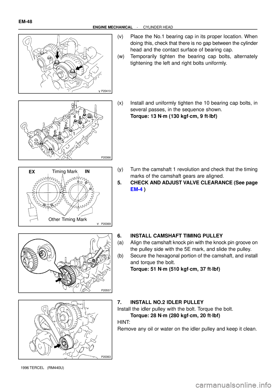
(v) Place the No.1 bearing cap in its proper location. When
doing this, check that there is no gap between the cylinder
head and the contact surface of bearing cap.
(w) Temporarily tighten the bearing cap bolts, alternately
tightening the left and right bolts uniformly.
(x) Install and uniformly tighten the 10 bearing cap bolts, in
several passes, in the sequence shown.
Torque: 13 N´m (130 kgf´cm, 9 ft´lbf)
(y) Turn the camshaft 1 revolution and check that the timing
marks of the camshaft gears are aligned.
5. CHECK AND ADJUST VALVE CLEARANCE (See page
EM-4)
6. INSTALL CAMSHAFT TIMING PULLEY
(a) Align the camshaft knock pin with the knock pin groove on
the pulley side with the 5E mark, and slide the pulley.
(b) Secure the hexagonal portion of the camshaft, and install
and torque the bolt.
Torque: 51 N´m (510 kgf´cm, 37 ft´lbf)
7. INSTALL NO.2 IDLER PULLEY
Install the idler pulley with the bolt. Torque the bolt.
Torque: 28 N´m (280 kgf´cm, 20 ft´lbf)
HINT:
Remove any oil or water on the idler pulley and keep it clean.
Page 471 of 1202
P20948
P20953
Timing Mark
Installation
Mark
P20746
P20748
P20749
- ENGINE MECHANICALCYLINDER HEAD
EM-49
1996 TERCEL (RM440U)
8. SET NO.1 CYLINDER TO TDC/COMPRESSION
(a) Turn the crankshaft pulley, and align its groove with timing
mark º0º of the No.1 timing belt cover.
(b) Turn the camshaft, and align the hole of the camshaft tim-
ing pulley on the side with the 5E mark with the timing
mark of the bearing cap.
9. INSTALL TIMING BELT
(a) Starting from the right hand side of the pulley and instal-
ling the belt counterclockwise.
(b) Loosen the No.1 idler pulley mounting bolt until the pulley
is moved slightly by the spring tension.
(c) Turn the crankshaft pulley 2 revolutions from TDC to TDC.
NOTICE:
Always turn the crankshaft clockwise.
Page 472 of 1202

P20538
Timing Mark
Installation Mark
P20361
P20286
Seal Packing
P20406
EM-50
- ENGINE MECHANICALCYLINDER HEAD
1996 TERCEL (RM440U)
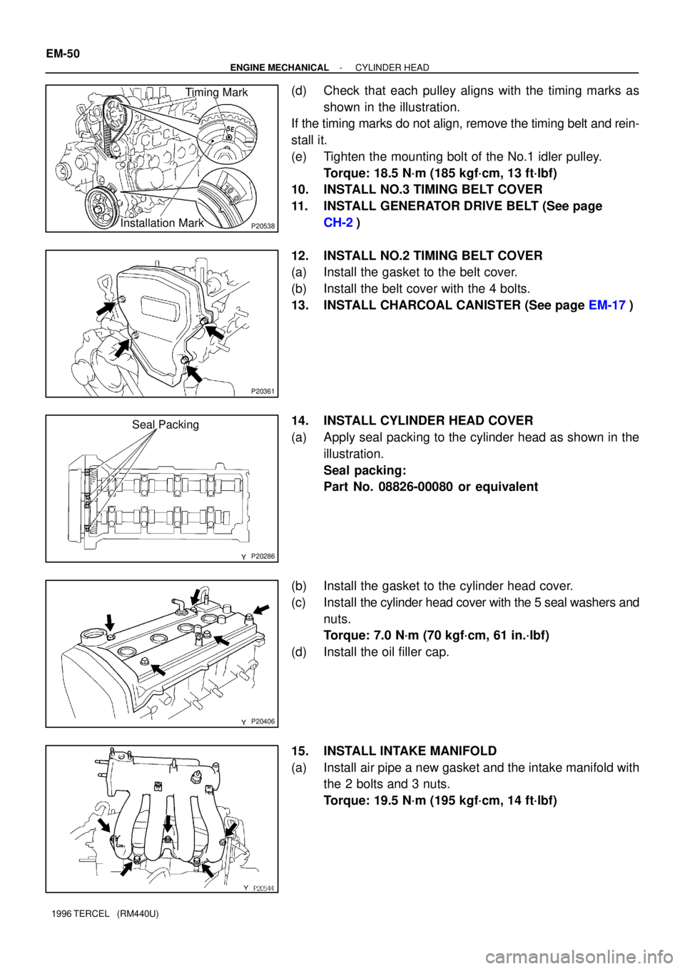
(d) Check that each pulley aligns with the timing marks as
shown in the illustration.
If the timing marks do not align, remove the timing belt and rein-
stall it.
(e) Tighten the mounting bolt of the No.1 idler pulley.
Torque: 18.5 N´m (185 kgf´cm, 13 ft´lbf)
10. INSTALL NO.3 TIMING BELT COVER
11. INSTALL GENERATOR DRIVE BELT (See page
CH-2)
12. INSTALL NO.2 TIMING BELT COVER
(a) Install the gasket to the belt cover.
(b) Install the belt cover with the 4 bolts.
13. INSTALL CHARCOAL CANISTER (See page EM-17)
14. INSTALL CYLINDER HEAD COVER
(a) Apply seal packing to the cylinder head as shown in the
illustration.
Seal packing:
Part No. 08826-00080 or equivalent
(b) Install the gasket to the cylinder head cover.
(c) Install the cylinder head cover with the 5 seal washers and
nuts.
Torque: 7.0 N´m (70 kgf´cm, 61 in.´lbf)
(d) Install the oil filler cap.
15. INSTALL INTAKE MANIFOLD
(a) Install air pipe a new gasket and the intake manifold with
the 2 bolts and 3 nuts.
Torque: 19.5 N´m (195 kgf´cm, 14 ft´lbf)
Page 473 of 1202

P20543
P20496
P20747
P20529
Seal PackingCORRECT WRONG
- ENGINE MECHANICALCYLINDER HEAD
EM-51
1996 TERCEL (RM440U)
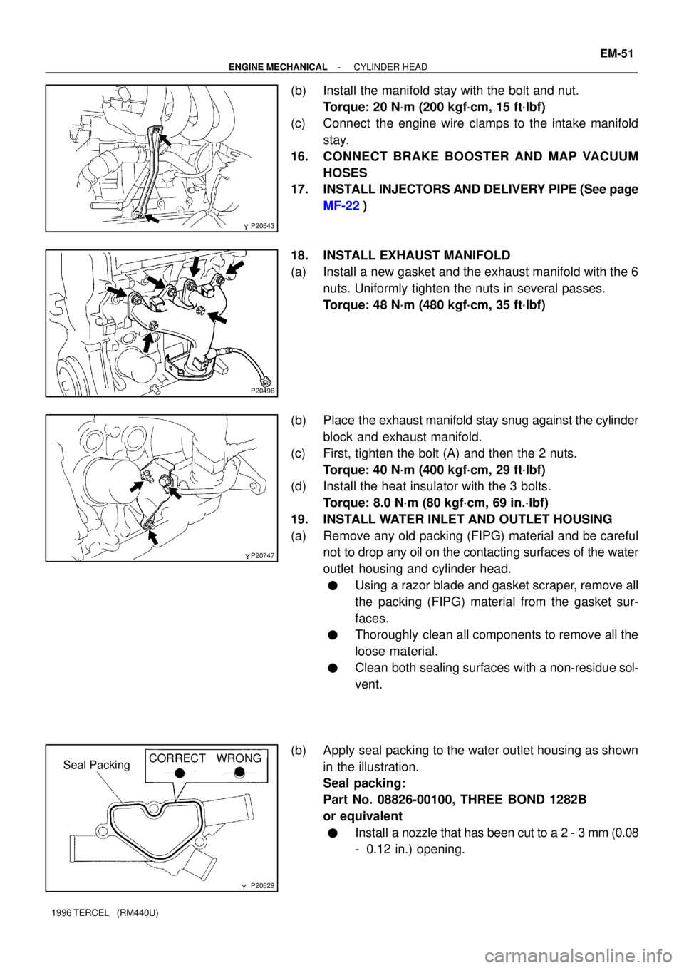
(b) Install the manifold stay with the bolt and nut.
Torque: 20 N´m (200 kgf´cm, 15 ft´lbf)
(c) Connect the engine wire clamps to the intake manifold
stay.
16. CONNECT BRAKE BOOSTER AND MAP VACUUM
HOSES
17. INSTALL INJECTORS AND DELIVERY PIPE (See page
MF-22)
18. INSTALL EXHAUST MANIFOLD
(a) Install a new gasket and the exhaust manifold with the 6
nuts. Uniformly tighten the nuts in several passes.
Torque: 48 N´m (480 kgf´cm, 35 ft´lbf)
(b) Place the exhaust manifold stay snug against the cylinder
block and exhaust manifold.
(c) First, tighten the bolt (A) and then the 2 nuts.
Torque: 40 N´m (400 kgf´cm, 29 ft´lbf)
(d) Install the heat insulator with the 3 bolts.
Torque: 8.0 N´m (80 kgf´cm, 69 in.´lbf)
19. INSTALL WATER INLET AND OUTLET HOUSING
(a) Remove any old packing (FIPG) material and be careful
not to drop any oil on the contacting surfaces of the water
outlet housing and cylinder head.
�Using a razor blade and gasket scraper, remove all
the packing (FIPG) material from the gasket sur-
faces.
�Thoroughly clean all components to remove all the
loose material.
�Clean both sealing surfaces with a non-residue sol-
vent.
(b) Apply seal packing to the water outlet housing as shown
in the illustration.
Seal packing:
Part No. 08826-00100, THREE BOND 1282B
or equivalent
�Install a nozzle that has been cut to a 2 - 3 mm (0.08
- 0.12 in.) opening.
Page 474 of 1202

EM-52
- ENGINE MECHANICALCYLINDER HEAD
1996 TERCEL (RM440U)
HINT:
Avoid applying an excess amount to the surface. Be especially
careful near oil passages.
�Parts must be assembled within 15 minutes of ap-
plication. Otherwise, the material must be removed
and reapplied.
�Immediately remove nozzle from tube and reinstall
cap.
�Do not pour in any coolant until at least 2 hours after
installation is completed.
(c) Install the water outlet housing with the bolt and 2 nuts.
Torque: 17.5 N´m (175 kgf´cm, 13 ft´lbf)
(d) Connect the 2 radiator hoses.
(e) Connect the water inlet hose.
(f) Connect the heater outlet hose.
(g) Connect the engine coolant temperature sensor connec-
tor.
(h) Connect the engine coolant temperature sender gauge
connector.
(i) Connect the fan engine coolant temperature switch con-
nector.
20. INSTALL CAMSHAFT POSITION SENSOR AND EGR
VSV
(a) Install a new O-ring to the position sensor.
(b) Install the position sensor with the bolt.
Torque: 8.0 N´m (80 kgf´cm, 69 in.´lbf)
(c) Install the EGR VSV with the bolt.
Torque: 17.5 N´m (175 kgf´cm, 13 in.´lbf)
(d) Connect the position sensor and EGR VSV connectors.
21. INSTALL EGR VALVE AND VACUUM MODULATOR
(a) Install a new gasket and the EGR valve with the 2 nuts.
Torque: 30 N´m (300 kgf´cm, 22 in.´lbf)
(b) Install the EGR vacuum modulator and bracket with the
bolt.