Page 879 of 1202

INSPECTION
1. MEASURE PAD LINING THICKNESS
Using a ruler, measure the pad lining thickness.
Standard thickn")
BR0RS-07
BR4362
BR4237
BR4238
BR4221
BR-26
- BRAKEFRONT BRAKE CALIPER
1996 TERCEL (RM440U)
INSPECTION
1. MEASURE PAD LINING THICKNESS
Using a ruler, measure the pad lining thickness.
Standard thickness: 10.0 mm (0.394 in.)
Minimum thickness: 1.0 mm (0.039 in.)
Replace the pad if the pad's thickness is at the minimum thick-
ness or less, or if the pad has severe and uneven wear.
2. MEASURE DISC THICKNESS
Using a micrometer, measure the disc thickness.
Standard thickness: 18.0 mm (0.709 in.)
Minimum thickness: 17.0 mm (0.689 in.)
Replace the disc if the disc's thickness is at the minimum thick-
ness or less. Replace the disc or grind it on a lathe if it is badly
scored or worn unevenly.
3. MEASURE DISC RUNOUT
Using a dial indicator, measure disc runout 10 mm (0.39 in.)
away from the outer.
Maximum disc runout: 0.07 mm (0.0028 in.)
If the disc's runout is the maximum value or greater, check the
bearing play is in the axial direction and check the axle hub run-
out (See page SA-10). If the bearing play and axle hub runout
are not abnormal, adjust the disc runout or grind it on a ºOn-carº
brake late.
4. IF NECESSARY, ADJUST DISC RUNOUT
(a) Remove the torque plate from the knuckle.
(b) Remove the hub nuts and the disc. Reinstall the disc in
the position turned 1/4 from its original position on the
hub. Install and torque the hub nuts.
Torque: 103 N´m (1,050 kgf´cm, 76 ft´lbf)
Remeasure the disc runout. Make a note of the runout and the
disc's position on the hub.
(c) Repeat (b) until the disc has been installed on the 2 re-
maining hub positions.
(d) If the minimum runout recorded in (b) and (c) is less than
0.07 mm (0.0028 in.), install the disc in that position.
(e) If the minimum runout recorded in (b) and (c) is greater
than 0.07 mm (0.0028 in.), replace the disc and repeat
step 3.
(f) Install the torque plate and fighten the 2 bolts.
Torque: 88 N´m (900 kgf´cm, 65 ft´lbf)
Page 884 of 1202
BR4387
BR3027
SST
BR0370
- BRAKEREAR DRUM BRAKE
BR-31
1996 TERCEL (RM440U)
(d) Using pliers, disconnect the parking brake cable from the
parking brake lever and remove the rear shoe.
6. REMOVE AUTOMATIC ADJUSTING LEVER AND
PARKING BRAKE LEVER
(a) Remove the E-ring.
(b) Remove the automatic adjusting lever.
(c) Remove the C-washer.
(d) Remove the parking brake lever.
7. REMOVE WHEEL CYLINDER
(a) Using SST, disconnect the brake line. Use a container to
catch the brake fluid.
SST 09751-3601 1
Torque: 15 N´m (155 kgf´cm, 11 ft´lbf)
(b) Remove the 2 bolts and the wheel cylinder.
Torque: 10 N´m (100 kgf´cm, 7 ft´lbf)
8. DISASSEMBLE WHEEL CYLINDER
Remove the these parts from the wheel cylinder.
�2 boots
�2 pistons
�2 piston cups
�Spring
Page 892 of 1202
BR0S2-07
- BRAKEABS ACTUATOR
BR-39
1996 TERCEL (RM440U)
REMOVAL
1. DISCONNECT CONNECTORS
(a) Disconnect the 2 connectors from the control relay.
(b) Disconnect the 2 connectors from the ABS actuator.
(c) Remove the control relay from the clamp.
2. DISCONNECT BRAKE LINES
Using SST, disconnect the 6 brake lines from the ABS actuator
assembly.
SST 09023-00100
Torque: 15 N´m (155 kgf´cm, 11 ft´lbf)
3. REMOVE ABS ACTUATOR ASSEMBLY
(a) Remove the RH front fender linner.
(b) Remove the 2 bolts, nut and ABS actuator assembly.
Torque: 19 N´m (195 kgf´cm, 14 ft´lbf)
4. REMOVE ABS ACTUATOR
(a) Remove the bolt and No.3 bracket from the ABS actuator
assembly.
Torque: 19 N´m (195 kgf´cm, 14 in.´lbf)
(b) Remove the 3 nuts and actuator from the bracket assem-
bly.
Torque: 5.4 N´m (55 kgf´cm, 48 in.´lbf)
(c) Remove the 3 holders and cushions from the ABS actua-
tor.
Page 895 of 1202
BR0S5-06
R04569
R04570
BR-42
- BRAKEFRONT SPEED SENSOR
1996 TERCEL (RM440U)
REMOVAL
1. DISCONNECT SPEED SENSOR CONNECTOR
(a) Remove the fender liner.
(b) Disconnect the speed sensor connector.
2. REMOVE SPEED SENSOR
(a) Remove the 2 clamp bolts and a clip holding the sensor
harness to the body and shock absorber.
Torque: 5.0 N´m (51 kgf´cm, 44 in.´lbf)
(b) Remove the bolt and speed sensor from the steering
knuckle.
Torque: 8.0 N´m (82 kgf´cm, 71 in.´lbf)
Page 898 of 1202
BR0S8-06
R04572
R04573
- BRAKEREAR SPEED SENSOR
BR-45
1996 TERCEL (RM440U)
REMOVAL
1. DISCONNECT SPEED SENSOR CONNECTOR
(a) Remove the rear seat cushion.
(b) Disconnect the speed sensor connector, and pull out the
sensor wire harness with the grommet.
(c) Remove the 3 clamp bolts holding the sensor wire har-
ness to the suspension arm.
Torque: 5.0 N´m (51 kgf´cm, 44 in.´lbf)
2. REMOVE SPEED SENSOR
Remove the bolt and speed sensor from the axle beam.
Torque: 8.0 N´m (82 kgf´cm, 71 in.´lbf)
Page 902 of 1202

DRIVE BELT
INSPECTION
1. CHECK D")
Z00038
DENSO BorroughsSR1F5-01
CH0087
CORRECT
WRONG
WRONG
R11541
PS Vane
Pump
CORRECTWRONG C
D
E
F
- STEERINGDRIVE BELT
SR-3
923 Author�: Date�:
1996 TERCEL (RM440U)
DRIVE BELT
INSPECTION
1. CHECK DRIVE BELT TENSION
Using a belt tension gauge, measure the belt tension.
Belt tension gauge:
DENSO BTG-20 (95506-00020) or
Borroughs No. BT-33-73F
Drive belt tension:
New belt: 140 - 180 lbf
Used belt: 80 - 120 lbf
NOTICE:
After installing the belt, check that it fits properly in the
ribbed grooves.
HINT:
�ºNew beltº refers to a belt which has been used less than
5 minutes on a running engine.
�ºUsed beltº refers to a belt which has been used on a run-
ning engine for 5 minutes or more.
2. VEHICLES WITH BELT TENSION ADJUSTING BOLT:
ADJUST DRIVE BELT TENSION
(a) Loosen the bolts A and B.
(b) Loosen the lock nuts D and E.
(c) Adjust adjusting bolt F so that its protrusion above nut C
is ± 0 mm (0 in.).
(d) Fix nut C using lock nut D.
(e) Push up the PS pump body so that there is no free play
in the belt. Turn adjusting bolt F to obtain the play in the
correct belt tension as specified above.
NOTICE:
Ensure that the pump body and nut C are positioned cor-
rectly, as shown before turning bolt F to adjust the bet ten-
sion.
(f) Torque the bolt A.
Torque: 43 N´m (440 kgf´cm, 32 ft´lbf)
Page 903 of 1202
SR-4
- STEERINGDRIVE BELT
924 Author�: Date�:
1996 TERCEL (RM440U)
(g) Torque the bolt B.
Torque: 43 N´m (440 kgf´cm, 32 ft´lbf)
(h) Loosen adjusting bolt F by 4 or 5 turns.
NOTICE:
Check that there is a gap of 5 mm (0.20 in.) or more between
the tip of nut C and the pump body.
(i) Fix adjusting bolt F with lock nut E.
(j) Recheck the belt tension.
Page 909 of 1202
SR4208
Maximum
Freeplay
30 mm (1.18 in.)SR05R-1 1
R12030
SR-10
- STEERINGSTEERING WHEEL
930 Author�: Date�:
1996 TERCEL (RM440U)
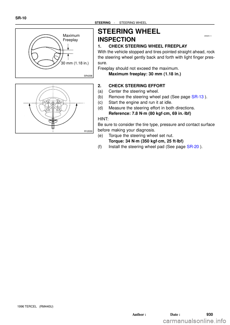
STEERING WHEEL
INSPECTION
1. CHECK STEERING WHEEL FREEPLAY
With the vehicle stopped and tires pointed straight ahead, rock
the steering wheel gently back and forth with light finger pres-
sure.
Freeplay should not exceed the maximum.
Maximum freeplay: 30 mm (1.18 in.)
2. CHECK STEERING EFFORT
(a) Center the steering wheel.
(b) Remove the steering wheel pad (See page SR-13).
(c) Start the engine and run it at idle.
(d) Measure the steering effort in both directions.
Reference: 7.8 N´m (80 kgf´cm, 69 in.´lbf)
HINT:
Be sure to consider the tire type, pressure and contact surface
before making your diagnosis.
(e) Torque the steering wheel set nut.
Torque: 34 N´m (350 kgf´cm, 25 ft´lbf)
(f) Install the steering wheel pad (See page SR-20).

(d) Using pliers, disconnect the parking brake cable from the
parking brake lever and remove the rear shoe.
6. REMOVE AUTOM")

REMOVAL
1. DISCONNECT CONNECTORS
(a) Disconnect the 2 connectors from the control relay.
(b) Disconnect the 2 connectors from the ABS actuator")

REMOVAL
1. DISCONNECT SPEED SENSOR CONNECTOR
(a) Remove the fender liner.
(b) Disconnect the speed sensor connector.
2. RE")

REMOVAL
1. DISCONNECT SPEED SENSOR CONNECTOR
(a) Remove the rear seat cushion.
(b) Disconnect the speed sensor connector,")