Page 833 of 1202
SA118-03
N00187
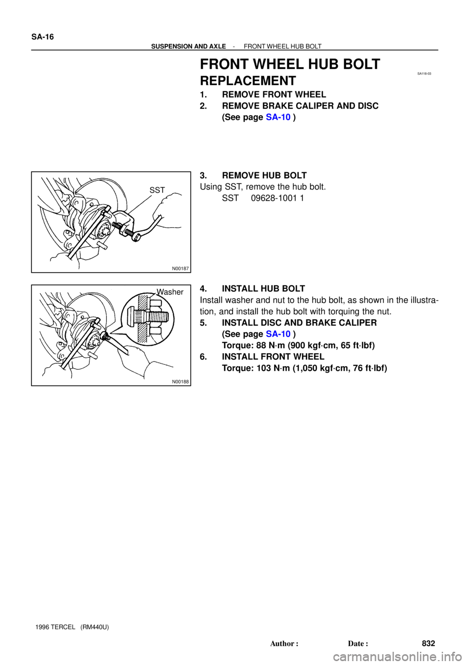
SST
N00188
Washer SA-16
- SUSPENSION AND AXLEFRONT WHEEL HUB BOLT
832 Author�: Date�:
1996 TERCEL (RM440U)
FRONT WHEEL HUB BOLT
REPLACEMENT
1. REMOVE FRONT WHEEL
2. REMOVE BRAKE CALIPER AND DISC
(See page SA-10)
3. REMOVE HUB BOLT
Using SST, remove the hub bolt.
SST 09628-1001 1
4. INSTALL HUB BOLT
Install washer and nut to the hub bolt, as shown in the illustra-
tion, and install the hub bolt with torquing the nut.
5. INSTALL DISC AND BRAKE CALIPER
(See page SA-10)
Torque: 88 N´m (900 kgf´cm, 65 ft´lbf)
6. INSTALL FRONT WHEEL
Torque: 103 N´m (1,050 kgf´cm, 76 ft´lbf)
Page 835 of 1202

REMOVAL
NOTICE:
�The hub bearing could be damaged if it is subjected
to the vehicle weight, such as when")
SA128-02
FA1535
SST
F03986
SA-18
- SUSPENSION AND AXLEFRONT DRIVE SHAFT
1996 TERCEL (RM440U)
REMOVAL
NOTICE:
�The hub bearing could be damaged if it is subjected
to the vehicle weight, such as when moving the ve-
hicle with the drive shaft removed. Therefore, if it is
absolutely necessary to place the vehicle weight on
the hub bearing, first support it with SST.
SST 09608-16042 (09608-02021, 09608-02041)
�w/ ABS:
After disconnecting the drive shaft from the axle hub,
work carefully so as not to damage the sensor rotor
serrations on the drive shaft.
1. REMOVE FRONT WHEEL
Torque: 103 N´m (1,050 kgf´cm, 76 ft´lbf)
2. M/T:
REMOVE LH ENGINE UNDER COVER
3. DRAIN TRANSAXLE OIL (M/T) OR ATF (A/T)
4. w/ ABS:
REMOVE BOLT AND ABS SPEED SENSOR
Torque: 7.8 N´m (80 kgf´cm, 69 in.´lbf)
5. REMOVE DRIVE SHAFT LOCK NUT
(a) Remove the cotter pin and lock cap.
(b) While applying the brakes, remove the nut.
Torque: 216 N´m (2,200 kgf´cm, 159 ft´lbf)
6. DISCONNECT TIE ROD END FROM STEERING
KNUCKLE (See page SA-10)
7. DISCONNECT LOWER BALL JOINT FROM LOWER
SUSPENSION ARM (See page SA-10)
8. DISCONNECT DRIVE SHAFT FROM AXLE HUB
NOTICE:
Be careful not to damage the drive shaft boot and inner oil
seal.
Page 842 of 1202
SA1W8-02
- SUSPENSION AND AXLEFRONT SHOCK ABSORBER
SA-25
1996 TERCEL (RM440U)
REMOVAL
1. REMOVE FRONT WHEEL
Torque: 103 N´m (1,050 kgf´cm, 76 ft´lbf)
2. REMOVE FLEXIBLE HOSE
Remove the bolt and disconnect the flexible hose from the shock absorber.
Torque: 29 N´m (300 kgf´cm, 22 ft´lbf)
3. w/ ABS:
DISCONNECT ABS SPEED SENSOR WIRE HARNESS
Remove the bolt and disconnect the ABS speed sensor wire harness from the shock absorber.
Torque: 5.4 N´m (55 kgf´cm, 48 in.´lbf)
4. DISCONNECT SHOCK ABSORBER FROM STEERING KNUCKLE
Remove the 2 nuts and bolts and disconnect the shock absorber from steering knuckle,
Torque: 245 N´m (2,500 kgf´cm, 181 ft´lbf)
HINT:
Coat the nut's threads with engine oil.
5. REMOVE SHOCK ABSORBER AND COIL SPRING
(a) Remove the 3/4 nuts on the upper side of the shock absorber.
Torque: 39 N´m (400 kgf´cm, 29 ft´lbf)
(b) Remove the shock absorber with the coil spring.
Page 846 of 1202
SA1WA-01
W03399
SST
W03400
MP Grease
SST
- SUSPENSION AND AXLEFRONT SHOCK ABSORBER
SA-29
1996 TERCEL (RM440U)
REASSEMBLY
1. INSTALL LOWER INSULATOR ONTO SHOCK AB-
SORBER
2. INSTALL COIL SPRING AND SUSPENSION SUPPORT
(a) Using SST, compress the coil spring.
SST 09727-30021
NOTICE:
Do not use an impact wrench. It will damage the SST.
(b) Install the spring bumper to the piston rod.
(c) Install the coil spring to the shock absorber.
HINT:
Fit the lower end of the coil spring into the gap of the spring seat
of shock absorber.
(d) Install the spring seat with the upper insulator.
(e) Install the dust seal and suspension support.
(f) Using SST, to hold the spring seat, install a new nut.
SST 09729-22031
Torque: 47 N´m (475 kgf´cm, 39 ft´lbf)
(g) Remove the SST.
(h) Pack the suspension support with MP grease.
(i) Install the cap.
Page 849 of 1202
SA11H-04
R11688
Z14904
SA-32
- SUSPENSION AND AXLEFRONT LOWER SUSPENSION ARM
1996 TERCEL (RM440U)
REMOVAL
1. REMOVE FRONT WHEEL
Torque: 103 N´m (1,050 kgf´cm, 76 ft´lbf)
2. DISCONNECT LOWER SUSPENSION ARM FROM
LOWER BALL JOINT
Remove the 2 nuts and bolt.
Torque: 80 N´m (820 kgf´cm, 59 ft´lbf)
3. REMOVE LOWER SUSPENSION ARM
Remove the 3 bolts, lower suspension arm.
Torque:
A: 142 N´m (1,450 kgf´cm, 105 ft´lbf)
B: 74 N´m (750 kgf´cm, 55 ft´lbf)
HINT:
After stabilizing the suspension, torque the bolts.
Page 852 of 1202
SA11K-01
SA3121
SST
- SUSPENSION AND AXLEFRONT LOWER BALL JOINT
SA-35
1996 TERCEL (RM440U)
REMOVAL
1. REMOVE STEERING KNUCKLE WITH AXLE HUB
(See page SA-10)
2. REMOVE LOWER BALL JOINT
(a) Remove the clip and nut.
Torque: 98 N´m (1,000 kgf´cm, 72 ft´lbf)
(b) Using SST, remove the lower ball joint.
SST 09628-6201 1
Page 853 of 1202
SA11L-05
N00208
SA-36
- SUSPENSION AND AXLEFRONT LOWER BALL JOINT
1996 TERCEL (RM440U)
INSPECTION
INSPECT LOWER BALL JOINT FOR ROTATION CONDI-
TION
(a) As shown flip the ball joint stud back and forth 5 times, be-
fore installing the nut.
(b) Using a torque wrench, turn the nut continuously one turn
per 2 - 4 seconds and take the torque reading on the 5th
turn.
Turning torque:
0.78 - 2.45 N´m (8 - 25 kgf´cm, 7.0 - 22.0 in.´lbf)
Page 859 of 1202

BRAKE PEDAL
ON-VEHICLE INSPECTION
1. CHECK PEDAL HEIGHT
Pedal heigh")
R12354
Stop Light Switch
Push Rod
Pedal Height
BR4980
A
BR1DT-01
BR-6
- BRAKEBRAKE PEDAL
880 Author�: Date�:
1996 TERCEL (RM440U)
BRAKE PEDAL
ON-VEHICLE INSPECTION
1. CHECK PEDAL HEIGHT
Pedal height from asphalt sheet:
EZ Grade:
143.0 - 153.0 mm (5.630 - 6.024 in.)
Except EZ Grade:
140.0 - 150.0 mm (5.512 - 5.906 in.)
If the pedal height is incorrect, adjust it.
2. IF NECESSARY, ADJUST PEDAL HEIGHT
(a) Disconnect the connector from the stop light switch.
(b) Loosen the stop light switch lock nut and remove the stop
light switch.
(c) Loosen the push rod lock nut.
(d) Adjust the pedal height by turning the pedal push rod.
(e) Tighten the push rod lock nut.
Torque: 25 N´m (260 kgf´cm, 19 ft´lbf)
(f) Install the stop light switch and turn it until it lightly con-
tacts the pedal stopper.
(g) Turn the stop light switch back one turn.
(h) Check the clearance (A) between stop light switch and
pedal.
Clearance: 0.5 - 2.4 mm (0.020 - 0.094 in.)
(i) Tighten the stop light switch lock nut.
(j) Connect the connector to the stop light switch.
(k) Check the stop lights come on when the brake pedal is de-
pressed, and go off when the brake pedal is released.
(l) After adjusting the pedal height, check the pedal freeplay.
HINT:
If clearance (A) between the stop light switch and the brack ped-
al stopper has been adjusted correctly, the pedal freeplay will
meet the specifications.

REMOVAL
1. REMOVE FRONT WHEEL
Torque: 103 N´m (1,050 kgf´cm, 76 ft´lbf)
2. REMOVE FLEXIBLE HOSE
Remove the bolt and d")

REASSEMBLY
1. INSTALL LOWER INSULATOR ONTO SHOCK AB-
SORBER
2. INSTALL COIL SPRING AND S")

REMOVAL
1. REMOVE FRONT WHEEL
Torque: 103 N´m (1,050 kgf´cm, 76 ft´lbf)
2. DISCONNECT LOWER SUSPE")

REMOVAL
1. REMOVE STEERING KNUCKLE WITH AXLE HUB
(See page SA-10)
2. REMOVE LOWER BALL JOINT
(a) Remove the")

INSPECTION
INSPECT LOWER BALL JOINT FOR ROTATION CONDI-
TION
(a) As shown flip the ball joint stud back and for")