Page 458 of 1202

P20379
P20385
P20386
EG0008
EM-36
- ENGINE MECHANICALCYLINDER HEAD
1996 TERCEL (RM440U)
9. INSPECT CAMSHAFTS AND BEARINGS
Inspect the camshaft for runout.
(1) Place the camshaft on V-blocks.
(2) Using a dial indicator, measure the circle runout at
the center journal.
Maximum circle runout: 0.04 mm (0.0016 in.)
If the circle runout is greater than maximum, replace the cam-
shaft.
10. INSPECT CAM LOBES
Using a micrometer, measure the cam lobe height.
Standard cam lobe height:
Intake41.514 - 41.614 mm (1.6344 - 1.6383 in.)
Exhaust41.011 - 41.111 mm (1.6146 - 1.6185 in.)
Minimum cam lobe height:
Intake41.35 mm (1.6279 in.)
Exhaust40.85 mm (1.6083 in.)
If the cam lobe height is less than minimum, replace the cam-
shaft.
11. INSPECT CAMSHAFT JOURNALS
Using a micrometer, measure the journal diameter.
Journal diameter:
Exhaust No.124.949 - 24.965 mm (0.9822 - 0.9829 in.)
Others22.949 - 22.965 mm (0.9035 - 0.9041 in.)
If the journal diameter is not as specified, check the oil clear-
ance.
12. INSPECT CAMSHAFT BEARINGS
Check that bearings for flaking and scoring.
If the bearings are damaged, replace the bearing caps and cyl-
inder head as a set.
Page 466 of 1202

P20389
Gasket
EM1OG-01
P20419
EX
(A)
Bi-Hexagon Wrench
(B)IN
(B)
(A)(B)
(B)(B)
(B)
8
61 3
9
10 4 257
(A) (A) (A)(A) IN
EX
P20413
Painted Mark
90°
P20174
(b)(c)
(d)(e)
EM-44
- ENGINE MECHANICALCYLINDER HEAD
1996 TERCEL (RM440U)
INSTALLATION
1. PLACE CYLINDER HEAD ON CYLINDER BLOCK
(a) Place a new cylinder head gasket in position on the cylin-
der block.
NOTICE:
Be careful of the installation direction.
(b) Place the cylinder head in position on the cylinder head
gasket.
2. INSTALL CYLINDER HEAD BOLTS
HINT:
�The cylinder head bolts are tightened in 2 progressive
steps (steps (b) and (d)).
�If any cylinder head bolt is broken or deformed, replace
it.
�There are 2 lengths of cylinder head bolts, long (A) and
short (B).
(a) Apply a light coat of engine oil on the threads and under
the heads of the cylinder head bolts.
(b) First, using a bi-hexagon wrench 8 mm, install and uni-
formly tighten the 10 cylinder head bolts, in several
passes, in the sequence shown.
Torque: 45 N´m (450 kgf´cm, 33 ft´lbf)
If any one of the cylinder head bolts does not meet the torque
specification, replace the cylinder head bolt.
(c) Mark the front of the cylinder head bolt head with paint.
(d) Retighten the cylinder head bolts 90° in the numerical or-
der shown.
(e) Check that the painted mark is now at a 90° angle to front.
3. ASSEMBLE INTAKE CAMSHAFT
(a) Mount the hexagonal wrench head portion of the cam-
shaft in a vise.
NOTICE:
Be careful not to damage the camshaft.
(b) Install the camshaft gear spring.
(c) Install the camshaft sub-gear.
(d) Install the wave washer.
HINT:
Align the pins on the gears with the gear spring ends.
Page 467 of 1202

P20418
Main Gear
Sub-GearSST
P00400
No.3 Cylinder
No.4 Cylinder
P20378
8
6 13
24
57
- ENGINE MECHANICALCYLINDER HEAD
EM-45
1996 TERCEL (RM440U)
(e) Using snap ring pliers, install the snap ring.
(f) Using SST, align the holes of the camshaft main gear and
sub-gear by turning camshaft sub-gear clockwise, and
install a service bolt.
SST 09960-10010 (09962-01000, 09963-00500)
4. INSTALL INTAKE AND EXHAUST CAMSHAFTS
NOTICE:
Since the thrust clearance of the camshaft is small, the
camshaft must be kept level while it is being installed. If the
camshaft is not kept level, the portion of the cylinder head
receiving the shaft thrust may crack or be damaged, caus-
ing the camshaft to seize or break. To avoid this, the follow-
ing steps should be carried out.
(a) Apply engine oil to the thrust portion of intake camshaft.
(b) Place the intake camshaft as shown in the illustration so
that the service bolt of the intake camshaft gears are di-
rectly above.
HINT:
This helps to lift the intake camshaft in a level and uniform man-
ner by pushing No.3 and No.4 cylinder cam lobes of the intake
camshaft toward their vale lifters.
(c) Install the 4 bearing caps in their proper locations.
(d) Temporarily tighten the bearing cap bolts uniformly and
alternately, in several passes, in the sequence shown un-
til the bearing caps are snug with the cylinder head.
Page 471 of 1202
P20948
P20953
Timing Mark
Installation
Mark
P20746
P20748
P20749
- ENGINE MECHANICALCYLINDER HEAD
EM-49
1996 TERCEL (RM440U)
8. SET NO.1 CYLINDER TO TDC/COMPRESSION
(a) Turn the crankshaft pulley, and align its groove with timing
mark º0º of the No.1 timing belt cover.
(b) Turn the camshaft, and align the hole of the camshaft tim-
ing pulley on the side with the 5E mark with the timing
mark of the bearing cap.
9. INSTALL TIMING BELT
(a) Starting from the right hand side of the pulley and instal-
ling the belt counterclockwise.
(b) Loosen the No.1 idler pulley mounting bolt until the pulley
is moved slightly by the spring tension.
(c) Turn the crankshaft pulley 2 revolutions from TDC to TDC.
NOTICE:
Always turn the crankshaft clockwise.
Page 473 of 1202

P20543
P20496
P20747
P20529
Seal PackingCORRECT WRONG
- ENGINE MECHANICALCYLINDER HEAD
EM-51
1996 TERCEL (RM440U)
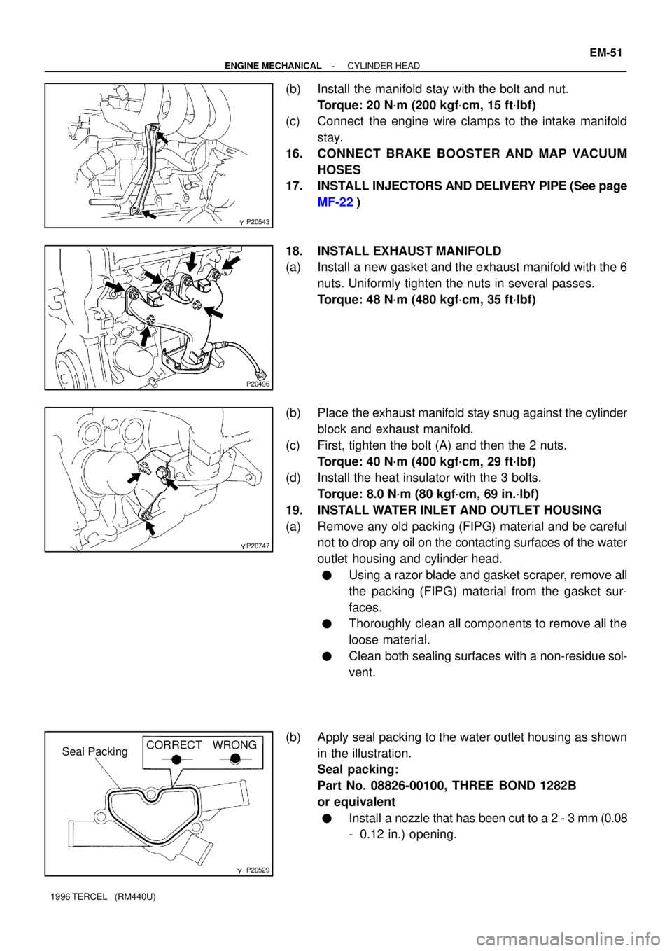
(b) Install the manifold stay with the bolt and nut.
Torque: 20 N´m (200 kgf´cm, 15 ft´lbf)
(c) Connect the engine wire clamps to the intake manifold
stay.
16. CONNECT BRAKE BOOSTER AND MAP VACUUM
HOSES
17. INSTALL INJECTORS AND DELIVERY PIPE (See page
MF-22)
18. INSTALL EXHAUST MANIFOLD
(a) Install a new gasket and the exhaust manifold with the 6
nuts. Uniformly tighten the nuts in several passes.
Torque: 48 N´m (480 kgf´cm, 35 ft´lbf)
(b) Place the exhaust manifold stay snug against the cylinder
block and exhaust manifold.
(c) First, tighten the bolt (A) and then the 2 nuts.
Torque: 40 N´m (400 kgf´cm, 29 ft´lbf)
(d) Install the heat insulator with the 3 bolts.
Torque: 8.0 N´m (80 kgf´cm, 69 in.´lbf)
19. INSTALL WATER INLET AND OUTLET HOUSING
(a) Remove any old packing (FIPG) material and be careful
not to drop any oil on the contacting surfaces of the water
outlet housing and cylinder head.
�Using a razor blade and gasket scraper, remove all
the packing (FIPG) material from the gasket sur-
faces.
�Thoroughly clean all components to remove all the
loose material.
�Clean both sealing surfaces with a non-residue sol-
vent.
(b) Apply seal packing to the water outlet housing as shown
in the illustration.
Seal packing:
Part No. 08826-00100, THREE BOND 1282B
or equivalent
�Install a nozzle that has been cut to a 2 - 3 mm (0.08
- 0.12 in.) opening.
Page 480 of 1202
P20565
M/T EM-58
- ENGINE MECHANICALENGINE UNIT
1996 TERCEL (RM440U)
�Engine coolant temperature sender gauge connec-
tor
�Engine coolant temperature sensor connector
�Camshaft position sensor connector
�EGR VSV
�Fan engine coolant temperature switch connector
�A/T only:
Lock-up solenoid connector
�A/T only:
Park/Neutral position switch connector
�M/T only:
Backup light switch connector
�A/T only:
No.2 vehicle speed sensor connector
�Ground strap
�Throttle position sensor connector
�IAC valve connector
�Injector connectors
�Crankshaft position sensor connector
�Knock sensor connector
�Starter connector and wire
�Generator connector and wire
15. M/T only:
REMOVE CLUTCH RELEASE CYLINDER WITHOUT
DISCONNECTING TUBE
(a) Remove the 3 bolts, release cylinder and tube from the
transaxle.
(b) Disconnect the ground strap.
16. M/T:
DISCONNECT CONTROL CABLE(S) FROM TRANS-
AXLE
(a) Remove the clip and plate washer.
(b) Remove the retainer from the cable.
Page 486 of 1202

P20336
P00356
P20164
P20292
EM-64
- ENGINE MECHANICALENGINE UNIT
1996 TERCEL (RM440U)
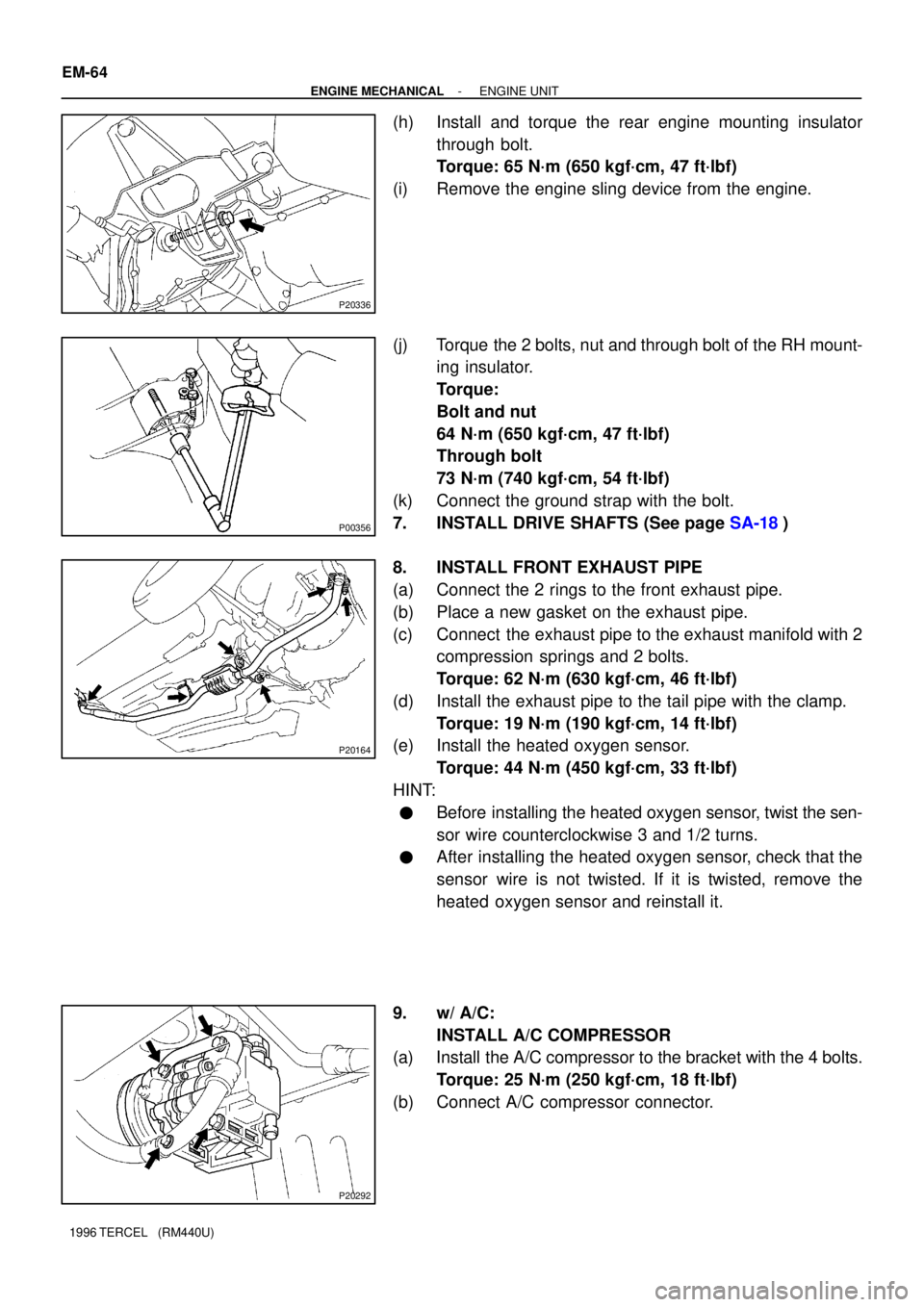
(h) Install and torque the rear engine mounting insulator
through bolt.
Torque: 65 N´m (650 kgf´cm, 47 ft´lbf)
(i) Remove the engine sling device from the engine.
(j) Torque the 2 bolts, nut and through bolt of the RH mount-
ing insulator.
Torque:
Bolt and nut
64 N´m (650 kgf´cm, 47 ft´lbf)
Through bolt
73 N´m (740 kgf´cm, 54 ft´lbf)
(k) Connect the ground strap with the bolt.
7. INSTALL DRIVE SHAFTS (See page SA-18)
8. INSTALL FRONT EXHAUST PIPE
(a) Connect the 2 rings to the front exhaust pipe.
(b) Place a new gasket on the exhaust pipe.
(c) Connect the exhaust pipe to the exhaust manifold with 2
compression springs and 2 bolts.
Torque: 62 N´m (630 kgf´cm, 46 ft´lbf)
(d) Install the exhaust pipe to the tail pipe with the clamp.
Torque: 19 N´m (190 kgf´cm, 14 ft´lbf)
(e) Install the heated oxygen sensor.
Torque: 44 N´m (450 kgf´cm, 33 ft´lbf)
HINT:
�Before installing the heated oxygen sensor, twist the sen-
sor wire counterclockwise 3 and 1/2 turns.
�After installing the heated oxygen sensor, check that the
sensor wire is not twisted. If it is twisted, remove the
heated oxygen sensor and reinstall it.
9. w/ A/C:
INSTALL A/C COMPRESSOR
(a) Install the A/C compressor to the bracket with the 4 bolts.
Torque: 25 N´m (250 kgf´cm, 18 ft´lbf)
(b) Connect A/C compressor connector.
Page 488 of 1202

EM-66
- ENGINE MECHANICALENGINE UNIT
1996 TERCEL (RM440U)
15. CONNECT ENGINE WIRE HARNESS
Connect these connectors and wires:
�Main heated oxygen sensor connector
�Oil pressure switch connector
�Engine coolant temperature sender gauge
connector
�Engine coolant temperature sensor connector
�Camshaft position sensor connector
�EGR VSV
�Fan engine coolant temperature switch connector
�A/T only:
Lock-up solenoid connector
�A/T only:
Park/Neutral position switch connector
�M/T only:
Backup light switch connector
�A/T only:
No.2 vehicle speed sensor connector
�Ground strap
�Throttle position sensor connector
�IAC valve connector
�Injector connectors
�Crankshaft position sensor connector
�Knock sensor connector
�Starter connector and wire
�Generator connector and wire
16. w/ PS:
CONNECT IDLE-UP AIR HOSES TO AIR CONTROL
VA LV E
17. CONNECT SPEEDOMETER CABLE
18. CONNECT HOSES
(a) Connect the brake booster vacuum hose.
(b) Connect the MAP sensor hose.
(c) Connect the heater hoses.