Page 509 of 1202

P20551
P20530
Front
Z14291
1
2 3
45
6
7
89
10
EM3480
P20569
Front Mark
(Cavity)
FrontPush
- ENGINE MECHANICALCYLINDER BLOCK
EM-87
1996 TERCEL (RM440U)
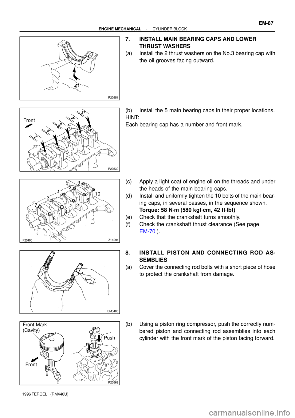
7. INSTALL MAIN BEARING CAPS AND LOWER
THRUST WASHERS
(a) Install the 2 thrust washers on the No.3 bearing cap with
the oil grooves facing outward.
(b) Install the 5 main bearing caps in their proper locations.
HINT:
Each bearing cap has a number and front mark.
(c) Apply a light coat of engine oil on the threads and under
the heads of the main bearing caps.
(d) Install and uniformly tighten the 10 bolts of the main bear-
ing caps, in several passes, in the sequence shown.
Torque: 58 N´m (580 kgf´cm, 42 ft´lbf)
(e) Check that the crankshaft turns smoothly.
(f) Check the crankshaft thrust clearance (See page
EM-70).
8. INSTALL PISTON AND CONNECTING ROD AS-
SEMBLIES
(a) Cover the connecting rod bolts with a short piece of hose
to protect the crankshaft from damage.
(b) Using a piston ring compressor, push the correctly num-
bered piston and connecting rod assemblies into each
cylinder with the front mark of the piston facing forward.
Page 510 of 1202

EM3481
Front Mark
(Protrusion)
Front
EM3448
P20475
Seal Packing
A'B'
A
B
A - A' B - B' EM-88
- ENGINE MECHANICALCYLINDER BLOCK
1996 TERCEL (RM440U)
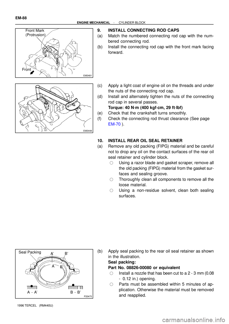
9. INSTALL CONNECTING ROD CAPS
(a) Match the numbered connecting rod cap with the num-
bered connecting rod.
(b) Install the connecting rod cap with the front mark facing
forward.
(c) Apply a light coat of engine oil on the threads and under
the nuts of the connecting rod cap.
(d) Install and alternately tighten the nuts of the connecting
rod cap in several passes.
Torque: 40 N´m (400 kgf´cm, 29 ft´lbf)
(e) Check that the crankshaft turns smoothly.
(f) Check the connecting rod thrust clearance (See page
EM-70).
10. INSTALL REAR OIL SEAL RETAINER
(a) Remove any old packing (FIPG) material and be careful
not to drop any oil on the contact surfaces of the rear oil
seal retainer and cylinder block.
�Using a razor blade and gasket scraper, remove all
the old packing (FIPG) material from the gasket sur-
faces and sealing groove.
�Thoroughly clean all components to remove all the
loose material.
�Using a non-residue solvent, clean both sealing
surfaces.
(b) Apply seal packing to the rear oil seal retainer as shown
in the illustration.
Seal packing:
Part No. 08826-00080 or equivalent
�Install a nozzle that has been cut to a 2 - 3 mm (0.08
- 0.12 in.) opening.
�Parts must be assembled within 5 minutes of ap-
plication. Otherwise the material must be removed
and reapplied.
Page 528 of 1202

P20175
New
Gasket
FI1654
Fulcrum Length
SST
30 cm
FI4295
CORRECT
WRONG
WRONG Delivery Pipe O-Ring
Grommet
Injector
FI4296
Delivery
Pipe
O-Ring
Grommet
InjectorCylinder Head
- MFIMFI SYSTEM
MF-3
527 Author�: Date�:
1996 TERCEL (RM440U)
(b) When connecting the union bolt on the high pressure pipe
union, observe these procedures:
(1) Always use 2 new gaskets.
(2) Tighten the union bolt by hand.
(3) Tighten the union bolt to the specified torque.
Torque: 29.0 N´m (290 kgf´cm, 22 ft´lbf)
(c) When connecting the flare nut on the high pressure pipe
union, observe these procedures:
(1) Apply a light coat of engine oil to the flare nut, and
tighten the flare nut by hand.
(2) Using SST, tighten the flare nut to specified torque.
SST 09631-22020
NOTICE:
Do not rotate the fuel pipe, when tightening the flare nut.
Torque: 30 N´m (300 kgf´cm, 23 ft´lbf)
HINT:
Use a torque wrench with a fulcrum length of 30 cm (11.81 in.).
(d) Observe these precautions when removing and installing
the injectors.
(1) Never reuse the O-ring.
(2) When placing a new O-ring on the injector, take
care not to damage it in any way.
(3) Coat a new O-ring with spindle oil or gasoline be-
fore installing-never use engine, gear or brake oil.
(e) Install the injector in the delivery pipe and cylinder head
as shown in the illustration.
Page 540 of 1202
SF1PU-02
- MFIFUEL PRESSURE REGULATOR
MF-15
1996 TERCEL (RM440U)
INSTALLATION
1. INSTALL FUEL PRESSURE REGULATOR
(a) Apply a light coat of gasoline to a new O-ring, and install
it to the pressure regulator.
(b) Attach the pressure regulator to the delivery pipe.
(c) Check that the pressure regulator rotates smothly.
NOTICE:
If it does not rotate smothly, the O-ring may be pinched, so
remove the pressure regulator and perform again steps (b)
and (c) above.
(d) Install the pressure regulator with the 3 bolts.
Torque:8.0 N´m (80kgf´cm, 69 in.´lbf)
2. CONNECT FUEL RETURN HOSE TO FUEL PRES-
SURE REGULATOR
3. CONNECT VACUUM SENSING HOSE TO FUEL PRES-
SURE REGULATOR
4. CHECK FOR FUEL LEAKS (See page MF-1)
Page 547 of 1202

SF0X4-05
FI3271
New
O-Ring
New Grommet
P00159
CORRECT
WRONG
InjectorDelivery Pipe GrommetO-Ring
WRONG
P20295
Spacer
Insulator
Connector MF-22
- MFIINJECTOR
1996 TERCEL (RM440U)
INSTALLATION
1. INSTALL INJECTORS AND DELIVERY PIPE
(a) Install a new grommet to the injector.
(b) Apply a light coat of gasoline to an O-ring, and install it
to the injector.
(c) While turning the injector left and right, install it to the de-
livery pipe. Install the 4 injectors.
(d) Place the 2 spacers and 4 insulators in position on the cyl-
inder head.
(e) Place the injectors together with the delivery pipe on the
cylinder head.
(f) Check that the injectors rotate smoothly.
HINT:
If the injectors do not rotate smoothly, the probable cause is in-
correct installation of O-rings. Replace the O-rings.
(g) Position the injector connector upward.
(h) Install the 2 bolts.
Torque: 19 N´m (190 kgf´cm, 14 ft´lbf)
2. CONNECT ENGINE WIRE
(a) Connect the 4 injector connectors.
(b) Connect the engine wire to the surge tank stay.
3. CONNECT FUEL INLET HOSE TO DELIVERY PIPE
(a) Install 2 new gaskets and the inlet hose with the union
bolt.
Torque: 30 N´m (300 kgf´cm, 23 ft´lbf)
(b) Connect the engine wire clamp to the No.2 engine hang-
er.
4. CONNECT FUEL RETURN HOSE TO FUEL RETURN
PIPE
5. CONNECT VACUUM SENSING HOSE TO FUEL PRES-
SURE REGULATOR
Page 599 of 1202
CO18B-01
CO1205
Dimension B
Stopper Bolt
Overhaul HandlePart A
ClawSST
P21090
Lock
Plate
Stopper BoltTank
P21091
CO-18
- COOLINGRADIATOR
1996 TERCEL (RM440U)
DISASSEMBLY
1. ASSEMBLE SST
SST 09230-01010
(a) Install the claw to the overhaul handle, inserting it in the
hole in part A as shown in the diagram.
(b) While gripping the handle, adjust the stopper bolt so that
dimension B is as shown in the diagram is 0.2 - 0.5 mm
(0.008 - 0.020 in.).
NOTICE:
If this adjustment is not performed, the claw may be dam-
aged.
2. UNCAULK LOCK PLATES
Using SST to release the caulking, squeeze the handle until
stopped by the stopper bolt.
SST 09230-01010
3. REMOVE TANKS AND O-RINGS
Lightly tap the radiator hose inlet (or outlet) with a soft-faced
hammer, and remove the tank.
Remove the O-ring.
4. A/T:
REMOVE OIL COOLER FROM LOWER TANK
(a) Remove the 2 nuts, spring washers, plate washers and oil
cooler.
(b) Remove the O-ring from the oil cooler.
Page 600 of 1202

CO0Y3-02
P21092
A
B
C
CO1267
Lock PlateLock Plate
Core
N00305
CORRECTWRONG
WRONG
P21093
CORRECT
WRONGTank
Lock
Plate
- COOLINGRADIATOR
CO-19
1996 TERCEL (RM440U)
REASSEMBLY
1. A/T:
INSTALL OIL COOLER TO LOWER TANK
(a) Clean the O-ring contact surface of the lower tank and oil
cooler.
(b) Install new O rings to the oil cooler.
(c) Install the oil cooler with the O-rings to the lower tank.
(d) Install the plate washers, spring washers and nuts.
Torque:
Nut A: 15 N´m (150 kgf´cm, 11 ft´lbf)
Nut B and C: 8.5 N´m (85 kgf´cm, 75 in.´lbf)
2. INSPECT LOCK PLATE
Inspect the lock plate for damage.
HINT:
�If the sides of the lock plate groove are deformed, reas-
sembly of the tank will be impossible.
�Therefore, first correct any deformation with pliers or like
object. Water leakage will result if the bottom of the lock
plate groove is damaged or dented or dented. There fore,
repair or replace if necessary.
3. INSTALL NEW O-RINGS AND TANKS
(a) After checking that there are no foreign objects in the lock
plate groove, install a new O-ring without twisting it.
HINT:
When cleaning the lock plate groove, lightly rub it with sand pa-
per without scratching it.
(b) Install the tank without damaging the O-ring.
(c) Tap the lock plate with a soft-faced hammer so that there
is no gap between it and the tank.
Page 601 of 1202
CO1206
Dimension B
Punch Assembly
Overhaul HandleStopper BoltPartSST
P21094
8 7
65
43
2
1
P21095
Stopper
BoltSSTTank
Lock
Plate
P21096
RibBracket
Claw
Z15037
CO-20
- COOLINGRADIATOR
1996 TERCEL (RM440U)
4. ASSEMBLE SST
SST 09230-01010
(a) Install the punch assembly to the overhaul handle, insert-
ing it in the hole in part A as shown in the illustration.
(b) While gripping the handle, adjust the stopper bolt so that
dimension B shown in the diagram is 7.7 mm (0.30 in.)
5. CAULK LOCK PLATE
(a) Lightly press SST against the lock plate in the order
shown in the illustration. After repeating this a few times,
fully caulk the lock plate by squeezing the handle until
stopped by the stopper plate.
SST 09230-01010
HINT:
�Do not stake the areas protruding around the ports,brack-
et or tank ribs.
�The oil cooler (A/T only) and the points attowed in the il-
lustlation cannot be staked with the SST. Use a plier or like
object and be careful not to damage the core plates.