Page 1351 of 2062
Downloaded from www.Manualslib.com manuals search engine Q00863
Q00864
MT−26
− MANUAL TRANSMISSION (W59)OUTPUT SHAFT
1996 TOYOTA T100 (RM449U)
(d) Using a micrometer, measure the outer diameter of the in-
ner race.
Minimum diameter: 42.975 mm (1.6919 in.)
If the outer diameter is less than the minimum, replace the inner
race.
(e) Using a dial indicator, check the shaft runout.
Maximum runout: 0.06 mm (0.0024 in.)
If the runout exceeds the maximum, replace the output shaft.
Page 1358 of 2062
Downloaded from www.Manualslib.com manuals search engine Q04038
Q04011
WM0066
− MANUAL TRANSMISSION (W59)COUNTER GEAR AND REVERSE IDLER GEAR
MT−33
1996 TOYOTA T100 (RM449U)
5. INSPECT 5TH GEAR SYNCHRONIZER RING
(a) Check for wear or damage.
(b) Install the synchronizer pull ring, cone ring and outer ring
to the 5th gear.
(c) Check the braking effect of the synchronizer ring. Turn the
synchronizer ring in one direction while pushing it to the
gear cone. Check that the ring locks.
If it does not lock, replace the synchronizer ring.
6. INSPECT SHIFT FORK AND HUB SLEEVE CLEAR-
ANCE
Using a feeler gauge, measure the clearance between the hub
sleeves and shift forks.
Maximum clearance: 1.0 mm (0.039 in.)
If the clearance exceeds the maximum, replace the shift fork or
hub sleeve.
Page 1359 of 2062
COUNTER GEAR AND REVERSE")
Downloaded from www.Manualslib.com manuals search engine MT03Z−01
WM0073
SST
Q06319
SST
Socket Wrench
RM0013
Socket Wrench
D00876
WM0079
MT−34
− MANUAL TRANSMISSION (W59)COUNTER GEAR AND REVERSE IDLER GEAR
1996 TOYOTA T100 (RM449U)
REPLACEMENT
1. IF NECESSARY, REPLACE COUNTER GEAR FRONT
BEARING AND SIDE RACE
(a) Using a snap ring expander, remove the snap ring.
(b) Using SST and a press, press out the bearing.
SST 09950−00020
(c) Check the side race for wear or damage.
(d) If necessary, remove the side race.
Using SST and a socket wrench, remove the side race.
SST 09950−40010
(e) Using a socket wrench and press, install a new bearing,
side race and inner race.
(f) Select a snap ring that allows the minimum axial play.
MarkThickness mm (in.)
A2.05 − 2.10 (0.0807 − 0.0827)
B2.10 − 2.15 (0.0827 − 0.0846)
C2.15 − 2.20 (0.0846 − 0.0866)
D2.20 − 2.25 (0.0866 − 0.0886)
E2.25 − 2.30 (0.0886 − 0.0906)
F2.30 − 2.35 (0.0906 − 0.0925)
(g) Using a snap ring expander, install the snap ring.
2. IF NECESSARY, REPLACE COUNTER GEAR CENTER
BEARING
(a) Remove the bearing from the counter gear.
(b) Install a new bearing on the counter gear.
HINT:
Engage the roller cages.
Page 1366 of 2062
EXTENSION HOUSING
MT−41
1996 T")
Downloaded from www.Manualslib.com manuals search engine MT044−01
Q04410
D00877
Reverse Restrict PinSlotted
Spring Pin
WM0085
Q07553
SST
− MANUAL TRANSMISSION (W59)EXTENSION HOUSING
MT−41
1996 TOYOTA T100 (RM449U)
REPLACEMENT
1. IF NECESSARY, REPLACE REVERSE RESTRICT PIN
(a) Remove the reverse restrict pin.
(1) Using a hexagon wrench, remove the screw plug.
(2) Using a pin punch and hammer, drive out the slotted
spring pin.
(3) Pull off the lever housing and slide out the shaft.
(b) Inspect the reverse restrict pin.
Turn and push the reverse restrict pin by hand.
Check for smooth operation.
(c) Install the reverse restrict pin.
(1) Install the lever housing.
(2) Using a pin punch and hammer, drive in the slotted
spring pin, as shown.
(3) Apply sealant to the plug threads.
Sealant:
Part No. 08833 − 00080, THREE BOND 1344, LOCTITE
242 or equivalent
(4) Install and torque the screw plug.
Torque: 25 N·m (250 kgf·cm, 18 ft·lbf)
2. IF NECESSARY, REPLACE REAR BEARING OUTER
RACE
(a) Using 2 screwdrivers, remove the snap ring.
(b) Using SST, remove the outer race.
SST 09308−00010
Page 1371 of 2062
Downloaded from www.Manualslib.com manuals search engine AT022−06
OR0004
SST
OR0005
SST
− AUTOMATIC TRANSMISSIONEXTENSION HOUSING OIL SEAL (A340E)
AT−3
1344 Author�: Date�:
1996 TOYOTA T100 (RM449U)
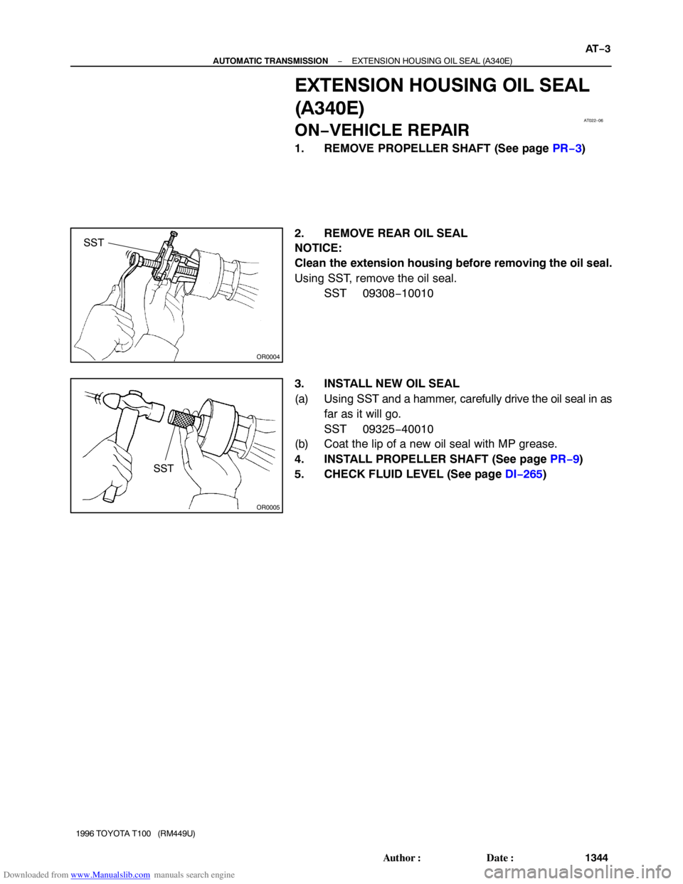
EXTENSION HOUSING OIL SEAL
(A340E)
ON−VEHICLE REPAIR
1. REMOVE PROPELLER SHAFT (See page PR−3)
2. REMOVE REAR OIL SEAL
NOTICE:
Clean the extension housing before removing the oil seal.
Using SST, remove the oil seal.
SST 09308−10010
3. INSTALL NEW OIL SEAL
(a) Using SST and a hammer, carefully drive the oil seal in as
far as it will go.
SST 09325−40010
(b) Coat the lip of a new oil seal with MP grease.
4. INSTALL PROPELLER SHAFT (See page PR−9)
5. CHECK FLUID LEVEL (See page DI−265)
Page 1379 of 2062
 SWITCH
AT−11
1352 Author�: Date�:
1996 TOYOTA T100 (RM449U)
PARK/NE")
Downloaded from www.Manualslib.com manuals search engine Q07624
AT01Y−01
− AUTOMATIC TRANSMISSIONPARK/NEUTRAL POSITION (PNP) SWITCH
AT−11
1352 Author�: Date�:
1996 TOYOTA T100 (RM449U)
PARK/NEUTRAL POSITION (PNP)
SWITCH
ON−VEHICLE REPAIR
1. DISCONNECT OIL COOLER PIPES
(See page A340E AT−28, A340F AT−34)
2. REMOVE PARK/NEUTRAL POSITION SWITCH
(a) Disconnect the connector.
(b) Pry off the lock washer and remove the nut.
(c) Remove the bolt and park/neutral position switch.
3. INSTALL PARK/NEUTRAL POSITION SWITCH
(a) Install the park/neutral position switch and bolt.
Torque: 13 N·m (130 kgf·cm, 9 ft·lbf)
(b) Install a new lock plate and the nut.
Torque: 3.9 N·m (40 kgf·cm, 35 in.·lbf)
(c) Bend claws on the lock plate to fix the nut.
(d) Connect the connector.
(e) Check that the engine can be started with the shift lever
only in the N or P position, but not in other positions.
If not as stated above, carry out the adjustment procedure.
(See page DI−265)
4. CONNECT OIL COOLER PIPES
(See page A340E AT−28, A340F AT−34)
5. TEST DRIVE VEHICLE
Page 1382 of 2062

AT1369
Z18882
AB
BA (A340E Only)
B
Z14778
A
B
A
B B
B A
A AT−14
− AUTOMATIC TRANSMISSIONVALVE BODY ASSEM")
Downloaded from www.Manualslib.com manuals search engine Z14779
Z18882
A
BB
BA (A340E Only)
AT1369
Z18882
AB
BA (A340E Only)
B
Z14778
A
B
A
B B
B A
A AT−14
− AUTOMATIC TRANSMISSIONVALVE BODY ASSEMBLY
1355 Author�: Date�:
1996 TOYOTA T100 (RM449U)
8. A340F:
REMOVE OIL PIPE
Pry up both pipe ends with a large screwdriver and remove the
pipe.
9. REMOVE VALVE BODY
(a) Remove the 17 (or 16) bolts.
Bolt length:
Bolt A: 23 mm (0.91 in.)
Bolt B: 32 mm (1.26 in.)
(b) Disconnect the throttle cable from the cam.
(c) Remove the valve body.
NOTICE:
Be careful not to drop the check ball body and spring.
10. INSTALL VALVE BODY
(a) Align the groove of the manual valve with the pin of the
lever.
(b) Connect the throttle cable cam.
(c) Check the springs into the accumulator pistons are
installed correctly.
(d) Install the 17 (or 16) bolts.
Torque: 10 N·m (100 kgf·cm, 7 ft·lbf)
Bolt length:
Bolt A: 23 mm (0.91 in.)
Bolt B: 32 mm (1.26 in.)
11. A340E:
INSTALL OIL PIPE
Using a plastic hammer, install the 2 pipes into the position, as
shown in the illustration.
NOTICE:
Be careful not to bend or damage the pipes.
Page 1384 of 2062
Downloaded from www.Manualslib.com manuals search engine AT1362
Seal Breadth
2 − 3 mm (0.08 − 0.12 in.)
Q07625
AT−16
− AUTOMATIC TRANSMISSIONVALVE BODY ASSEMBLY
1357 Author�: Date�:
1996 TOYOTA T100 (RM449U)
16. INSTALL OIL PAN
(a) A340E:
Install the 4 magnets.
(b) A340F:
Install the 6 magnets.
(c) Remove any packing material and be careful not to drop
oil on the contacting surfaces of the transmission case
and oil pan.
(d) Apply FIPG to the oil pan, as shown in the illustraiton.
FIPG: Part No. 08826−00090, THREE BOND 1281 or
equivalent
(e) Install the oil pan with the 19 bolts.
Torque: 7.4 N·m (75 kgf·cm, 65 in.·lbf)
17. INSTALL DRAIN PLUG
Torque: 20 N·m (205 kgf·cm, 15 ft·lbf)
18. FILL FLUID AND CHECK FLUID
OUTPUT SHAFT
1996 TOYOTA T100 (RM449U)
(d) Using a micrometer, measure the outer diameter")
COUNTER GEAR AND REVERSE IDLER GEAR
MT−33
1996 TOYOTA T100 (RM449U)
5. INSPECT 5TH GEAR S")