Page 1415 of 2062

DISASSEMBLY
1. REMOVE SPEEDOMETER DRIVEN")
Downloaded from www.Manualslib.com manuals search engine TR0CZ−01
TF0629
TF0447
Q09400
FIPG
− TRANSFERTRANSFER ASSEMBLY
TR−7
1996 TOYOTA T100 (RM449U)
DISASSEMBLY
1. REMOVE SPEEDOMETER DRIVEN GEAR
Torque: 11 N·m (115 kgf·cm, 8 ft·lbf)
2. REMOVE TRANSFER INDICATOR SWITCH
Torque: 37 N·m (380 kgf·cm, 27 ft·lbf)
3. A/T:
REMOVE TRANSFER L4 AND NEUTRAL POSITION
SWITCH
Torque: 37 N·m (380 kgf·cm, 27 ft·lbf)
HINT:
At the time of installation, check the following items.
�Check to see that the input shaft and output shafts rotate
smoothly.
�Check to see that shifting can be made smoothly to all
position.
4. A/T:
REMOVE SHIFT GEAR HEAD NO.1 AND NO.2
(a) Using a pin punch and hammer, drive out the 2 slotted
spring pins.
(b) Remove the 2 shift gear heads.
5. REMOVE FRONT RETAINER
(a) Remove the 7 bolts.
Torque: 12 N·m (120 kgf·cm, 9 ft·lbf)
HINT:
At the time of installation, apply liquid sealer to the bolts.
Sealant:
Part No.08833−00080, THREE BOND 1344,
LOCTITE 242 or equivalent
(b) Using a plastic hammer, tap the front retainer and remove
it.
HINT:
At the time of installation, please refer to the following items.
�Remove any FIPG material and be careful not to drop oil
on the contacting surfaces of the front retainer.
�Apply FIPG to the front retainer, as shown.
FIPG:
Part No.08826−00090, THREE BOND 1281,
LOCTITE 242 or equivalent
Page 1426 of 2062

DISASSEMBLY
1. CHECK OIL PUMP OPERATION
Install the oil")
Downloaded from www.Manualslib.com manuals search engine TR0D0−01
TF0547
TF0485
TR−18
− TRANSFEROIL PUMP BODY
1996 TOYOTA T100 (RM449U)
DISASSEMBLY
1. CHECK OIL PUMP OPERATION
Install the oil pump drive gear to the drive rotor and check that
the drive rotor turns smoothly.
2. REMOVE STRAIGHT SCREW PLUG, SPRING, BALL
AND SEAT
(a) Using a hexagon wrench, remove the straight screw plug.
Torque: 29 N·m (300 kgf·cm, 22 ft·lbf)
HINT:
At the time of installation, apply liquid sealer to the plug.
Sealant:
Part No. 08833−00080, THREE BOND 1344, LOCTITE
242 or equivalent
(b) Using a magnetic finger remove the spring and ball.
(c) Using SST, pull out the seat.
SST 09921−00010
(d) Remove the O−ring from the seat.
HINT:
At the time of reassembly, please refer to the following items.
�Install a new O−ing to the seat.
�When installing the seat, push the seat until it touches the
bottom of the hole in the body.
3. REMOVE OIL PUMP PLATE
(a) Using a torx socket wrench (T30), unscrew the 3 torx
screws.
Torque: 7.4 N·m (75 kgf·cm, 65 in.·lbf)
(b) Remove the oil pump plate.
4. REMOVE DRIVE ROTOR AND DRIVEN ROTOR
HINT:
At the time of reassembly, apply gear oil to the both rotors.
Page 1439 of 2062
Downloaded from www.Manualslib.com manuals search engine TR026−02
TF0535
TF0552
TF0536
− TRANSFERINPUT SHAFT
TR−31
1996 TOYOTA T100 (RM449U)
INSPECTION
1. REMOVE SUN GEAR
(a) Using snap ring pliers, remove the snap ring.
(b) Remove the sun gear from the input shaft.
2. INSPECT INPUT SHAFT
(a) Using a micrometer, measure the outer diameter of the in-
put shaft journal surface.
Minimum diameter: 47.59 mm (1.8736 in.)
(b) Using a dial indicator, measure the inside diameter of the
input shaft bushing.
Maximum inside diameter: 39.14 mm (1.5409 in.)
If the inside diameter exceeds the maximum, replace the input
shaft.
3. M/T:
INSPECT SYNCHRONIZER RING
(a) Turn the ring and push it in to check the braking action.
(b) Measure the clearance between the synchronizer ring
back and the input shaft spline end.
Standard clearance:
1.15 − 1.85 mm (0.0453 − 0.0728 in.)
Minimum clearance: 0.80 mm (0.0315 in.)
If the clearance is less than the minimum, replace the synchro-
nizer ring.
Page 1448 of 2062
Downloaded from www.Manualslib.com manuals search engine PR01F−01
− PROPELLER SHAFTTROUBLESHOOTING
PR−1
1419 Author�: Date�:
1996 TOYOTA T100 (RM449U)
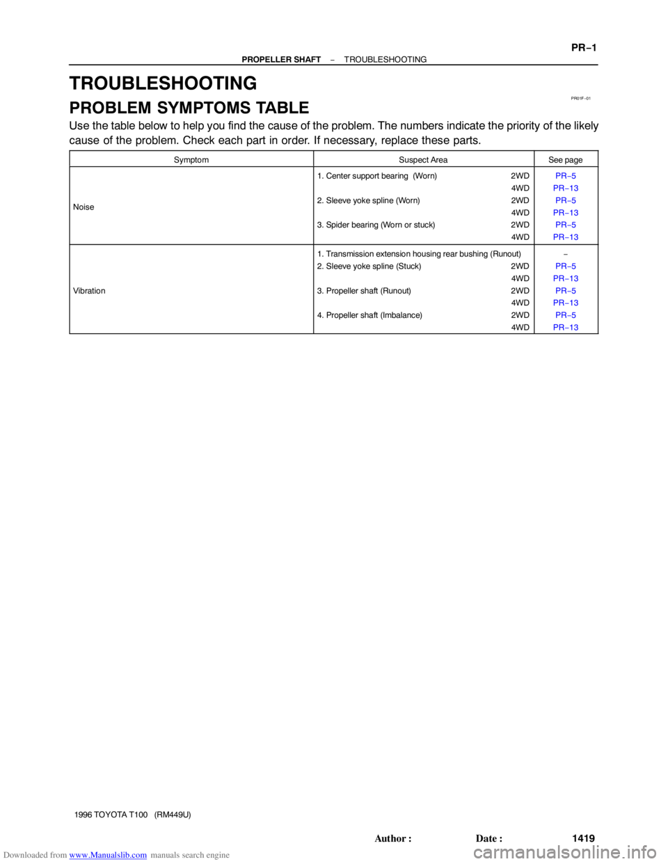
TROUBLESHOOTING
PROBLEM SYMPTOMS TABLE
Use the table below to help you find the cause of the problem. The numbers indicate the priority of the likely
cause of the problem. Check each part in order. If necessary, replace these parts.
SymptomSuspect AreaSee page
Noise
1. Center support bearing (Worn) 2WD
4WD
2. Sleeve yoke spline (Worn) 2WD
4WD
3. Spider bearing (Worn or stuck) 2WD
4WDPR−5
PR−13
PR−5
PR−13
PR−5
PR−13
Vibration
1. Transmission extension housing rear bushing (Runout)
2. Sleeve yoke spline (Stuck) 2WD
4WD
3. Propeller shaft (Runout) 2WD
4WD
4. Propeller shaft (Imbalance) 2WD
4WD−
PR−5
PR−13
PR−5
PR−13
PR−5
PR−13
Page 1452 of 2062
Downloaded from www.Manualslib.com manuals search engine PR01J−01
R04446
R04447
R04478
− PROPELLER SHAFTPROPELLER SHAFT ASSEMBLY (2WD)
PR−5
1996 TOYOTA T100 (RM449U)
INSPECTION
NOTICE:
Be careful not to grip the propeller shaft tube too tightly in
a vise as this will cause deformation.
1. INSPECT PROPELLER SHAFT AND INTERMEDIATE
SHAFT FOR DAMAGE OR RUNOUT
Using a dial indicator, check each runout of shaft.
Maximum runout: 0.8 mm (0.031 in.)
If shaft runout is greater than the maximum, replace the shaft.
2. INSPECT SPIDER BEARING
(a) Inspect the spider bearing for wear or damage.
(b) Using a dial indicator, check the spider bearing axial play
by turning the yoke of flange while holding the shaft tight-
ly.
Bearing axial play: 0.05 mm (0.0020 in.)
3. INSPECT CENTER SUPPORT BEARING FOR WEAR
OR DAMAGE
Check that the bearing turns freely.
If the bearing is damaged, worn, or does not turn freely, replace
it.
Page 1456 of 2062

Downloaded from www.Manualslib.com manuals search engine PR07Z−01
R15507Matchmarks
R04434
TMC
90Bracket Center
Line
Shaft Axial
Direction
R04435
DANA
90Bracket Center
Line
Shaft Axial
Direction
− PROPELLER SHAFTPROPELLER SHAFT ASSEMBLY (2WD)
PR−9
1996 TOYOTA T100 (RM449U)
INSTALLATION
1. INSTALL PROPELLER SHAFT
(a) Remove SST from the transmission.
SST 09325−40010
(b) Insert the yoke into the transmission.
(c) Temporarily install the center support bearing with 2
mounting bolts.
HINT:
Make sure the bearing is installed with facing the drain hole
downwards.
(d) Align the matchmarks on the flanges and connect the
flanges with the 4 bolts, washers and nuts.
(e) Torque the 4 bolts.
Torque: 74 N·m (750 kgf·cm, 54 ft·lbf)
2. ADJUST CENTER SUPPORT BEARING
HINT:
�With the vehicle unladen, adjust the center support bear-
ing to keep the intervals, as shown.
�At the same condition, check the center line in the axial
direction. Adjust the bearing if necessary.
�Check that the center line of the center bearing is set to
the center line of the bracket when the vehicle is unladen.
Adjust the bracket if necessary.
Torque the 2 bolts.
Torque: 36 N·m (370 kgf·cm, 27 ft·lbf)
Page 1460 of 2062

PR−13
1996 TOYOTA T100 (RM449U")
Downloaded from www.Manualslib.com manuals search engine PR01P−01
R04446
R04447
R04478
R04479
Double Cardan
Joint
− PROPELLER SHAFTPROPELLER SHAFT ASSEMBLY (4WD)
PR−13
1996 TOYOTA T100 (RM449U)
INSPECTION
NOTICE:
Be careful not to grip the propeller shaft tube too tightly in
a vise as this will cause deformation.
1. INSPECT PROPELLER SHAFT AND INTERMEDIATE
SHAFT FOR DAMAGE OR RUNOUT
Using a dial indicator, check the runout of shafts.
Maximum runout: 0.8 mm (0.031 in.)
If shaft runout is greater than the maximum, replace the shaft.
2. INSPECT SPIDER BEARING
(a) Inspect the spider bearing for wear or damage.
(b) Using a dial indicator, check the spider bearing axial play
by turning the yoke of flange while holding the shaft tight-
ly.
Bearing axial play: 0.05 mm (0.0020 in.)
3. INSPECT CENTER SUPPORT BEARING FOR WEAR
OR DAMAGE
Check that the bearing turns freely.
If the bearing is damaged, worn, or does not turn freely, replace
it.
HINT:
When replacing the rear propeller shaft spider, be sure that the
grease fitting assembly hole is facing in the direction shown in
the illustration.
4. INSPECT WITH DOUBLE CARDAN JOINT PROPEL-
LER SHAFT
(a) Inspect the shaft for wear or damage.
(b) Inspect the double cardan joint for wear damage.
If any problem is found, replace the propeller shaft assembly.
HINT:
Double cardan joint is used on front and rear propeller shafts.
Page 1464 of 2062
Downloaded from www.Manualslib.com manuals search engine R04482
Bracket Center
Line
90
Shaft Axial
Direction
− PROPELLER SHAFTPROPELLER SHAFT ASSEMBLY (4WD)
PR−17
1996 TOYOTA T100 (RM449U)
3. ADJUST CENTER SUPPORT BEARING
HINT:
�With the vehicle unladen, adjust the center support bear-
ing to keep the intervals, as shown.
�At the same condition, check the center line in the axial
direction. Adjust the bearing if necessary.
�Check that the center line of the center bearing is set to
the center line of the bracket when the vehicle is unladen.
Adjust the bracket if necessary.
(a) Torque the 2 bolts.
Torque: 36 N·m (370 kgf·cm, 27 ft·lbf)
(b) Install propeller shaft protector with 4 bolts.
Torque: 29 N·m (300 kgf·cm, 22 ft·lbf)

INSPECTION
1. REMOVE SUN GEAR
(a) Using snap ring p")

PR−5
1996 TOYOTA T100 (RM449U)
INSPECTION
NOTICE:
Be care")

PR−17
1996 TOYOTA T100 (RM449U)
3. AD")