Page 1075 of 2062
Downloaded from www.Manualslib.com manuals search engine Z15606
SF−56
− SFI (5VZ−FE)KNOCK SENSOR
1062 Author�: Date�:
1996 TOYOTA T100 (RM449U)
Page 1076 of 2062

Downloaded from www.Manualslib.com manuals search engine SF0CV−04
P21182
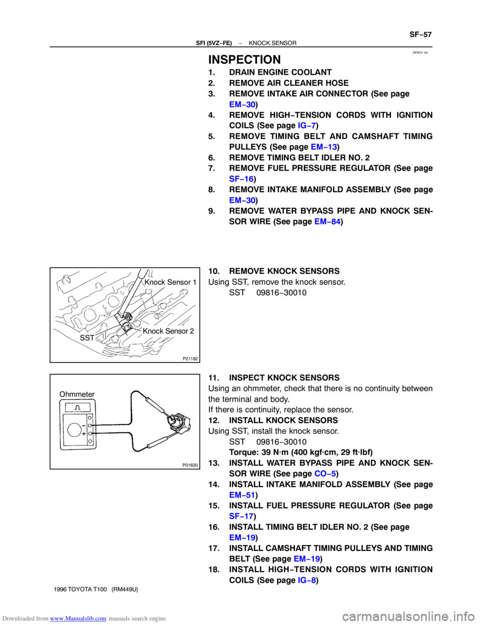
SSTKnock Sensor 1
Knock Sensor 2
P01630
Ohmmeter
− SFI (5VZ−FE)KNOCK SENSOR
SF−57
1996 TOYOTA T100 (RM449U)
INSPECTION
1. DRAIN ENGINE COOLANT
2. REMOVE AIR CLEANER HOSE
3. REMOVE INTAKE AIR CONNECTOR (See page
EM−30)
4. REMOVE HIGH−TENSION CORDS WITH IGNITION
COILS (See page IG−7)
5. REMOVE TIMING BELT AND CAMSHAFT TIMING
PULLEYS (See page EM−13)
6. REMOVE TIMING BELT IDLER NO. 2
7. REMOVE FUEL PRESSURE REGULATOR (See page
SF−16)
8. REMOVE INTAKE MANIFOLD ASSEMBLY (See page
EM−30)
9. REMOVE WATER BYPASS PIPE AND KNOCK SEN-
SOR WIRE (See page EM−84)
10. REMOVE KNOCK SENSORS
Using SST, remove the knock sensor.
SST 09816−30010
11. INSPECT KNOCK SENSORS
Using an ohmmeter, check that there is no continuity between
the terminal and body.
If there is continuity, replace the sensor.
12. INSTALL KNOCK SENSORS
Using SST, install the knock sensor.
SST 09816−30010
Torque: 39 N·m (400 kgf·cm, 29 ft·lbf)
13. INSTALL WATER BYPASS PIPE AND KNOCK SEN-
SOR WIRE (See page CO−5)
14. INSTALL INTAKE MANIFOLD ASSEMBLY (See page
EM−51)
15. INSTALL FUEL PRESSURE REGULATOR (See page
SF−17)
16. INSTALL TIMING BELT IDLER NO. 2 (See page
EM−19)
17. INSTALL CAMSHAFT TIMING PULLEYS AND TIMING
BELT (See page EM−19)
18. INSTALL HIGH−TENSION CORDS WITH IGNITION
COILS (See page IG−8)
Page 1077 of 2062
Downloaded from www.Manualslib.com manuals search engine SF−58
− SFI (5VZ−FE)KNOCK SENSOR
1996 TOYOTA T100 (RM449U)
19. INSTALL INTAKE AIR CONNECTOR (See page
EM−51)
20. INSTALL AIR CLEANER HOSE
21. FILL WITH ENGINE COOLANT
22. CHECK ENGINE COOLANT LEVEL
Page 1078 of 2062
Downloaded from www.Manualslib.com manuals search engine P21670
SF0D1−02
P21685
− SFI (5VZ−FE)EXHAUST GAS RECIRCULATION (EGR) GAS
TEMPERATURE SENSORSF−59
1065 Author�: Date�:
1996 TOYOTA T100 (RM449U)
EXHAUST GAS RECIRCULATION
(EGR) GAS TEMPERATURE
SENSOR
INSPECTION
1. REMOVE EGR GAS TEMPERATURE SENSOR
2. INSPECT EGR GAS TEMPERATURE SENSOR
Using an ohmmeter, measure the resistance between the ter-
minals.
Resistance:
64 − 97 kΩ at 50°C (122°F)
11 − 16 kΩ at 100°C (212°F)
2 − 4 kΩ at 150°C (302°F)
If the resistance is not as specified, replace the sensor.
3. REINSTALL EGR GAS TEMPERATURE SENSOR
Torque: 20 N·m (200 kgf·cm, 14 ft·lbf)
Page 1079 of 2062
Downloaded from www.Manualslib.com manuals search engine P21188
SF0CW−04
SF−60
− SFI (5VZ−FE)HEATED OXYGEN SENSOR
1066 Author�: Date�:
1996 TOYOTA T100 (RM449U)
HEATED OXYGEN SENSOR
INSPECTION
INSPECT HEATER RESISTANCE OF HEATED
OXYGEN SENSORS
(a) Disconnect the oxygen sensor connector.
(b) Using an ohmmeter, measure the resistance between the
terminals +B and HT.
Resistance:
M/T Bank 1 Sensor 1:
5 − 7 Ω at 20°C (68°F)
Others:
11 − 16 Ω at 20°C (68°F)
If the resistance is not as specified, replace the sensor.
Torque: 20 N·m (200 kgf·cm, 14 ft·lbf)
(c) Reconnect the oxygen sensor connector.
Page 1146 of 2062

Downloaded from www.Manualslib.com manuals search engine LU036−03
Z04119
SST SST
P20974
P20973
− LUBRICATION (5VZ−FE)OIL PUMP
LU−9
1996 TOYOTA T100 (RM449U)
REMOVAL
HINT:
When repairing the oil pump, the oil pan and strainer should be
removed and cleaned.
1. REMOVE CRANKSHAFT TIMING PULLEY
(See page EM−13)
2. 4WD:
REMOVE FRONT DIFFERENTIAL
3. DRAIN ENGINE OIL
4. A/T:
REMOVE OIL COOLER TUBE AND CLAMP
(See page AT−28)
5. REMOVE STIFFENER PLATE
6. REMOVE FLYWHEEL HOUSING UNDER AND COVER
DUST
7. DISCONNECT STARTER WIRE CLAMP
8. REMOVE CRANKSHAFT POSITION SENSOR
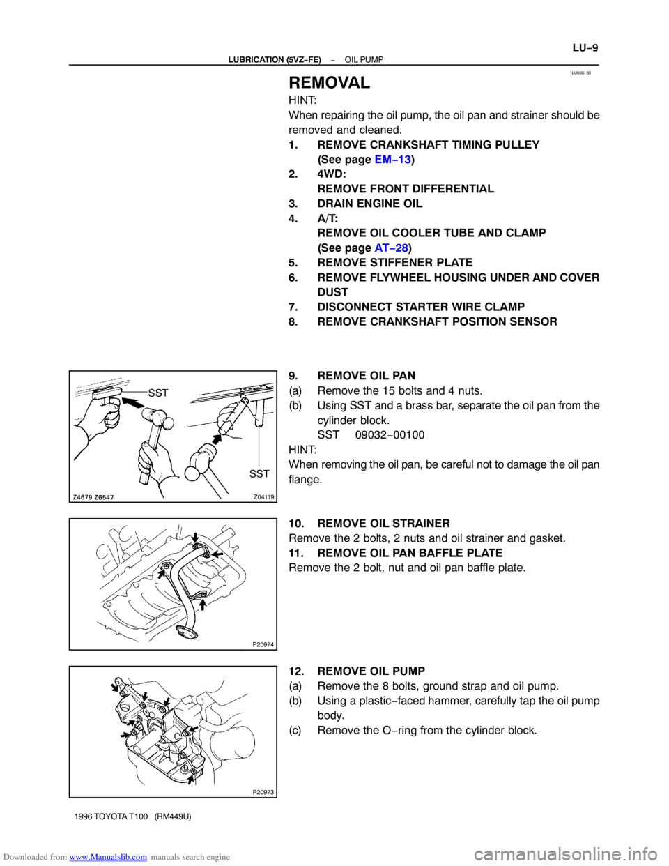
9. REMOVE OIL PAN
(a) Remove the 15 bolts and 4 nuts.
(b) Using SST and a brass bar, separate the oil pan from the
cylinder block.
SST 09032−00100
HINT:
When removing the oil pan, be careful not to damage the oil pan
flange.
10. REMOVE OIL STRAINER
Remove the 2 bolts, 2 nuts and oil strainer and gasket.
11. REMOVE OIL PAN BAFFLE PLATE
Remove the 2 bolt, nut and oil pan baffle plate.
12. REMOVE OIL PUMP
(a) Remove the 8 bolts, ground strap and oil pump.
(b) Using a plastic−faced hammer, carefully tap the oil pump
body.
(c) Remove the O−ring from the cylinder block.
Page 1152 of 2062

Downloaded from www.Manualslib.com manuals search engine Z14383B A
B
BB
B
B
LU0609
Seal Packing
− LUBRICATION (5VZ−FE)OIL PUMP
LU−15
1996 TOYOTA T100 (RM449U)
(e) Install the oil pump with the 8 bolts, and ground strap.
Torque:
Bolt A: 20 N·m (200 kgf·cm, 15 ft·lbf)
Bolt B: 42 N·m (420 kgf·cm, 31 ft·lbf)
2. INSTALL CRANK SHAFT POSITION SENSOR
3. INSTALL OIL PAN BAFFLE PLATE
4. INSTALL OIL STRAINER
Place a new gasket and install the oil strainer.
Torque:7.5 N·m (76 kgf·cm, 66 in.·lbf)
5. CLEAN OIL PAN
Remove any old packing (FIPG) material and be careful not to
drop any oil on the contacting surfaces of the, oil pan, cylinder
block and sealing grooves.
�Using a razor blade and gasket scraper, remove all
the remaining seal packing (FIPG) material from the
gasket surfaces.
�Thoroughly clean all components to remove all the
loose material.
�Clean both sealing surfaces with a non−residue sol-
vent.
NOTICE:
Do not use a solvent which will affect the painted surfaces.
6. INSTALL OIL PAN
(a) Apply seal packing to the oil pan, as shown in the illustra-
tion.
Seal packing:
Part No. 08826−00080 or equivalent
�Install a nozzle that has been cut to a 3 − 4 mm (0.12
− 0.16 in.) opening.
HINT:
Avoid applying an excess amount to the surface.
�If parts are not assembled within 5 minutes of apply-
ing the seal packing, the effectiveness of the seal
packing is lost and the seal packing must be re-
moved and reapplied.
�Immediately remove the nozzle from the tube and
reinstall the cap after using the seal packing.
(b) Install the oil pan with the 4 nuts and 15 bolts.
Torque:7.6 N·m (78 kgf·cm, 67 in.·lbf)
7. INSTALL FLYWHEEL HOUSING UNDER AND COVER
DUST
8. INSTALL STIFFENER PLATE
9. CONNECT STARTER WIRE CLAMP
10. A/T:
INSTALL OIL COOLER TUBE AND CLAMP
11. INSTALL CRANKSHAFT TIMING PULLEY
(See page EM−19)
Page 1158 of 2062
Downloaded from www.Manualslib.com manuals search engine IG – IGNITION (3RZ-FE)
IGNITION SYSTEM IG-1
DISTRIBUTOR IG-6
CRANKSHAFT POSITION SENSOR IG-13