Page 1689 of 2062
Downloaded from www.Manualslib.com manuals search engine BR09S−08
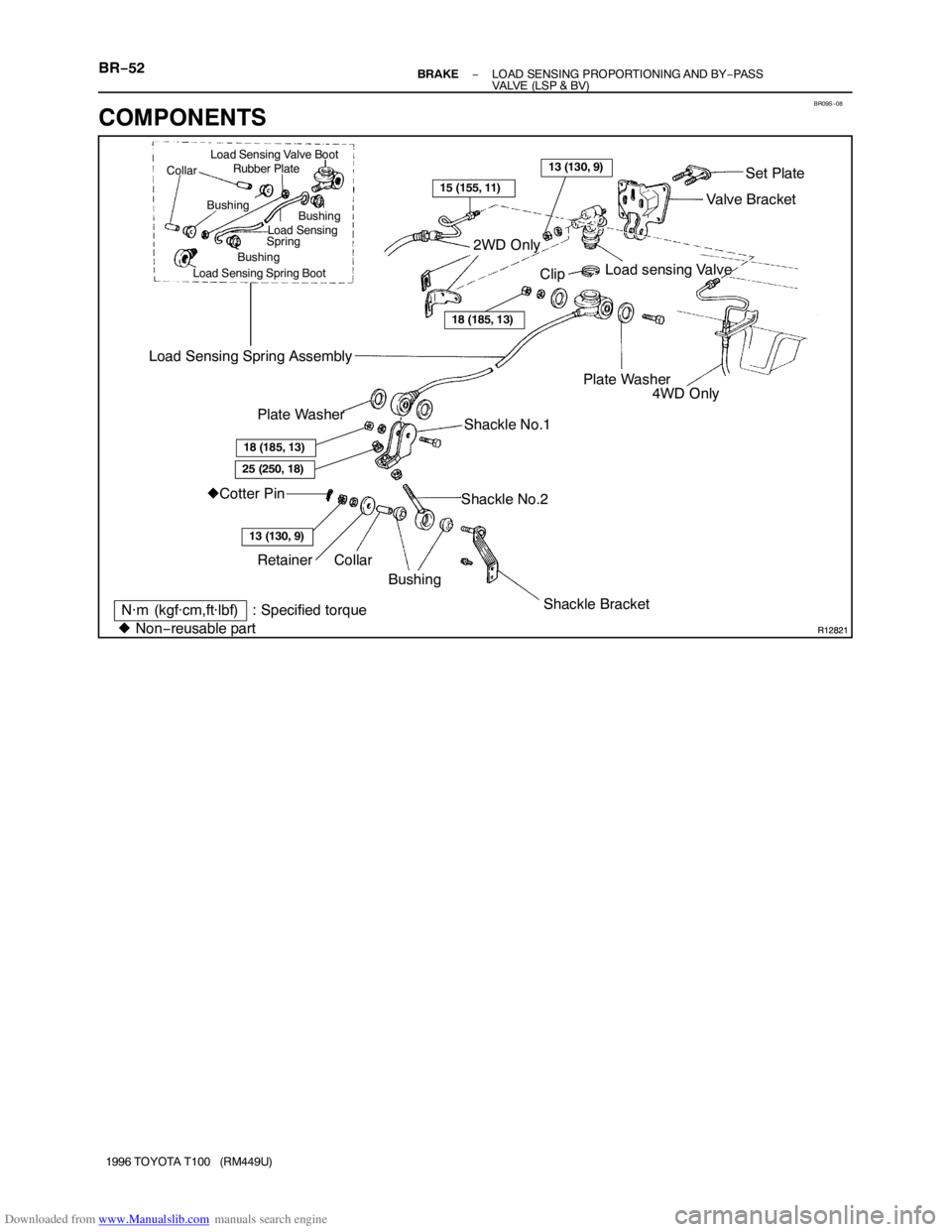
R12821
R12821
Shackle Bracket Shackle No.2Load sensing Valve
4WD Only
�Cotter Pin Load Sensing Spring AssemblyValve BracketN·m (kgf·cm,ft·lbf)
�Collar
BushingSet Plate
2WD Only
Clip
Plate Washer
Shackle No.1 Plate Washer
Non−reusable part
Load Sensing Valve Boot
Rubber Plate
Collar
Load Sensing Spring BootBushing Bushing
BushingLoad Sensing
Spring
15 (155, 11)
18 (185, 13)
13 (130, 9)
: Specified torque
18 (185, 13)
13 (130, 9)
Retainer
25 (250, 18)
BR−52− BRAKELOAD SENSING PROPORTIONING AND BY−PASS
VALVE (LSP & BV)
1996 TOYOTA T100 (RM449U)
COMPONENTS
Page 1690 of 2062
Downloaded from www.Manualslib.com manuals search engine BR09T−01
R09582
Z11332
SST
− BRAKELOAD SENSING PROPORTIONING AND BY−PASS
VALVE (LSP & BV)BR−53
1996 TOYOTA T100 (RM449U)
REMOVAL
1. DISCONNECT SHACKLE NO.2 FROM BRACKET
(a) Remove the cotter pin.
(b) Remove the nut and cushion retainer, and disconnect the
shackle No.2.
(c) Remove the 2 bushings and collar.
2. REMOVE LSP & BV ASSEMBLY
(a) Using SST, disconnect the brake lines from the valve
body.
SST 09751−36011
(b) Remove the valve bracket mounting bolts and the LSP &
BV assembly.
Page 1691 of 2062

Downloaded from www.Manualslib.com manuals search engine R09581
BR09U−02
BR1638
BR3338
BR0589
BR0070
Valve Side Shackle Side BR−54
− BRAKELOAD SENSING PROPORTIONING AND BY−PASS
VALVE (LSP & BV)
1996 TOYOTA T100 (RM449U)
DISASSEMBLY
1. REMOVE VALVE BRACKET
(a) Remove the nut and bolt.
CAUTION:
At the time of reassembly, please refer to the following
item. When connecting the shackle to the load sensing with
a bolt and nut, insert the bolt from the front side of vehicle.
Torque: 18 N·m (185 kgf·cm, 13 ft·lbf)
(b) Remove the 2 nuts, and remove the bracket and set plate
from the valve body.
HINT:
At the time of reassembly, please refer to the following item.
Finger tighten the valve body mounting nuts.
2. DISCONNECT SPRING FROM VALVE
Using pliers, remove the clip and the spring from the valve.
3. REMOVE SHACKLES NO.1 AND NO.2
(a) Remove the nuts and bolts, and then remove No.1 and
No.2 shackles and 2 plate washers from the load sensing
spring assembly.
Torque: 18 N·m (185 kgf·cm, 13 ft·lbf)
(b) Loosen the 2 nuts, remove the nut and shackle No.1 from
the shackle No.2.
4. DISASSEMBLE LOAD SENSING SPRING
Disassemble these parts:
�4 Bushings
�2 Collars
�2 Rubber plates
�Load sensing valve boot
�Load sensing spring boot
HINT:
At the time of reassembly, please refer to the following items.
�Apply lithium soap−base glycol grease to all rubbing
areas.
�Do not mistake the valve side for the shackle side of the
load sensing spring.
Page 1692 of 2062
Downloaded from www.Manualslib.com manuals search engine BR09V−01
Z03645
Wear Limit 0.7 mm
− BRAKELOAD SENSING PROPORTIONING AND BY−PASS
VALVE (LSP & BV)BR−55
1996 TOYOTA T100 (RM449U)
INSPECTION
INSPECT VALVE PISTON PIN AND LOAD SENSING CON-
TACT SURFACE FOR WEAR
Wear limit: 0.7 mm (0.028 in.)
Page 1693 of 2062
Downloaded from www.Manualslib.com manuals search engine BR09W−01
BR−56− BRAKELOAD SENSING PROPORTIONING AND BY−PASS
VALVE (LSP & BV)
1996 TOYOTA T100 (RM449U)
REASSEMBLY
Reassembly is in the reverse order of disassembly (See page BR−54).
Page 1694 of 2062
BR−57
1996 TOYOTA T100")
Downloaded from www.Manualslib.com manuals search engine BR09X−01
Z11332
SST
Z11333
A
BR0218
BR0061
SST
− BRAKELOAD SENSING PROPORTIONING AND BY−PASS
VALVE (LSP & BV)BR−57
1996 TOYOTA T100 (RM449U)
INSTALLATION
1. INSTALL LSP & BV ASSEMBLY TO FRAME
Torque: 29 N·m (300 kgf·cm, 22 ft·lbf)
2. CONNECT BRAKE LINE
Using SST, connect the brake lines.
Torque: 15 N·m (155 kgf·cm, 11 ft·lbf)
SST 09751−36011
3. CONNECT SHACKLE NO.2 BRACKET
(a) Install the shackle No.2 to the load sensing spring.
(b) Set dimension A and torque the lock nut.
Initial set: 120 mm (4.72 in.)
Torque: 25 N·m (250 kgf·cm, 18 ft·lbf)
(c) Connect the shackle No.2 to the shackle bracket.
Torque: 13 N·m (130 kgf·cm, 9 ft·lbf)
(d) Install a new cotter pin.
4. SET REAR AXLE LOAD
(See page BR−50)
5. SET VALVE BODY
(a) When pulling down the load sensing spring, check that
the valve piston moves down smoothly.
(b) Position the valve body so that the valve piston lightly
contacts with the load sensing spring.
(c) Tighten the valve body mounting nuts.
Torque: 13 N·m (130 kgf·cm, 9 ft·lbf)
6. BLEED BRAKE LINE (See page BR−4)
7. CHECK AND ADJUST LSP & BV FLUID PRESSURE
(See page BR−50)
8. APPLY SEALANT TO SHACKLE No.2
Apply sealant to the top portion of the shackle No.2 bolt threads
not to lose the upper lock nut.
Sealant:
Part No. 08833−00070, THREE BOND 1324 or equiva-
lent
Page 1695 of 2062

ABS ACTUATOR
ON−VEHICLE INSPECTION
1.")
Downloaded from www.Manualslib.com manuals search engine F14857
BR1NW−01
R07778
BR−58
− BRAKEABS ACTUATOR
1663 Author�: Date�:
1996 TOYOTA T100 (RM449U)
ABS ACTUATOR
ON−VEHICLE INSPECTION
1. INSPECT BATTERY POSITIVE VOLTAGE
Battery positive voltage: 10 − 14 V
2. DISCONNECT CONNECTORS
(a) Disconnect the 2 connectors from the control relay.
(b) Disconnect the connector from the actuator.
3. CONNECT ACTUATOR CHECKER (SST) TO ACTUA-
TOR
(a) Connect the actuator checker (SST) to the actuator, con-
trol relay and body side wire harness through the sub−
wire harness C and E (SST) as shown in the illustration.
SST 09990−00150, 09990−00200, 09990−00210
(b) Connect the red cable of the checker to the battery posi-
tive (+) terminal and black cable to the negative (−) termi-
nal. Connect the black cable of the sub−wire harnesses
to the battery negative (−) terminal or body ground.
(c) Place the ”SHEET L” (SST) on the actuator checker.
SST 09990−00370
4. INSPECT BRAKE ACTUATOR OPERATION
(a) Start the engine, and run it at idle.
(b) Turn the selector switch of the actuator checker in
”FRONT” position.
(c) Push and hold in the MOTOR switch for a few seconds.
Make sure that you can hear the motor running.
Page 1696 of 2062

(d) Depress the brake pedal and hold")
Downloaded from www.Manualslib.com manuals search engine R07779
R07780
R07781
R07782
− BRAKEABS ACTUATOR
BR−59
1664 Author�: Date�:
1996 TOYOTA T100 (RM449U)
(d) Depress the brake pedal and hold it until the step (g) is
completed.
(e) Push the POWER SWITCH, and check that the brake
pedal does not go down.
NOTICE:
Do not keep the POWER SWITCH pushed down for more
than 10 seconds.
(f) Release the switch, and check that the pedal goes down.
(g) Push and hold in the MOTOR switch for a few seconds,
and check that the pedal returns.
(h) Release the brake pedal.
(i) Push and hold in the MOTOR switch for a few seconds.
(j) Depress the brake pedal and hold it for about 15 seconds.
As you hold the pedal down, push the MOTOR switch for
a few seconds. Check that the brake pedal does not pul-
sate.
(k) Release the brake pedal.
5. INSPECT FOR OTHER WHEELS
(a) Change the connection of the actuator checker (SST) to
the sub − wire harness E (SST) − from the sub − wire har-
ness MAIN connector to the SUB connector, or vice ver-
sa.
(b) Repeating (c) to (i) of the step 4, check the actuator opera-
tion same way.
6. INSPECT FOR REAR WHEEL
(a) Turn the selector switch to the ”REAR” position.
(b) Push and hold in the MOTOR switch for a few seconds.
(c) Depress the brake pedal and hold it until the step (g) is
completed.
BR−53
1996 TOYOTA T100 (RM449U)
REMOVAL
1.")
BR−55
1996 TOYOTA T100 (RM449U)
INSP")

1996 TOYOTA T100 (RM449U)
REASSEMBLY
Reassembly is in")