Page 330 of 1354
S01261S01272A04480
DLC1
TE1
SST
E1
DI−10
− DIAGNOSTICSENGINE
1996 RAV4 (RM447U)
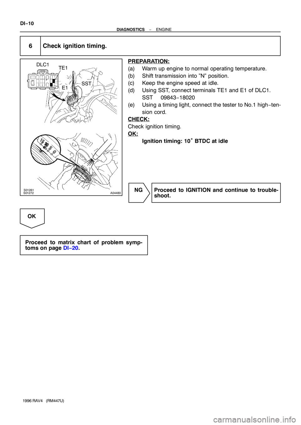
6 Check ignition timing.
PREPARATION:
(a) Warm up engine to normal operating temperature.
(b) Shift transmission into ”N” position.
(c) Keep the engine speed at idle.
(d) Using SST, connect terminals TE1 and E1 of DLC1.
SST 09843−18020
(e) Using a timing light, connect the tester to No.1 high−ten-
sion cord.
CHECK:
Check ignition timing.
OK:
Ignition timing: 10° BTDC at idle
NG Proceed to IGNITION and continue to trouble-
shoot.
OK
Proceed to matrix chart of problem symp-
toms on page DI−20.
Page 554 of 1354
R10638
DI98E−01
R06980
Short Pin
DLC1
F15316
E1
Tc DLC1
R01346
0.25 sec.
0.25 sec.
ON
OFF
ON
OFF0.5 sec.
4 sec.1.5
sec.2.5 sec.
Code 11Code 21
2 sec.
0.5 sec.
Codes 11 and 21Normal Code DI−234
− DIAGNOSTICSANTI−LOCK BRAKE SYSTEM
1996 RAV4 (RM447U)
PRE−CHECK
1. DIAGNOSIS SYSTEM
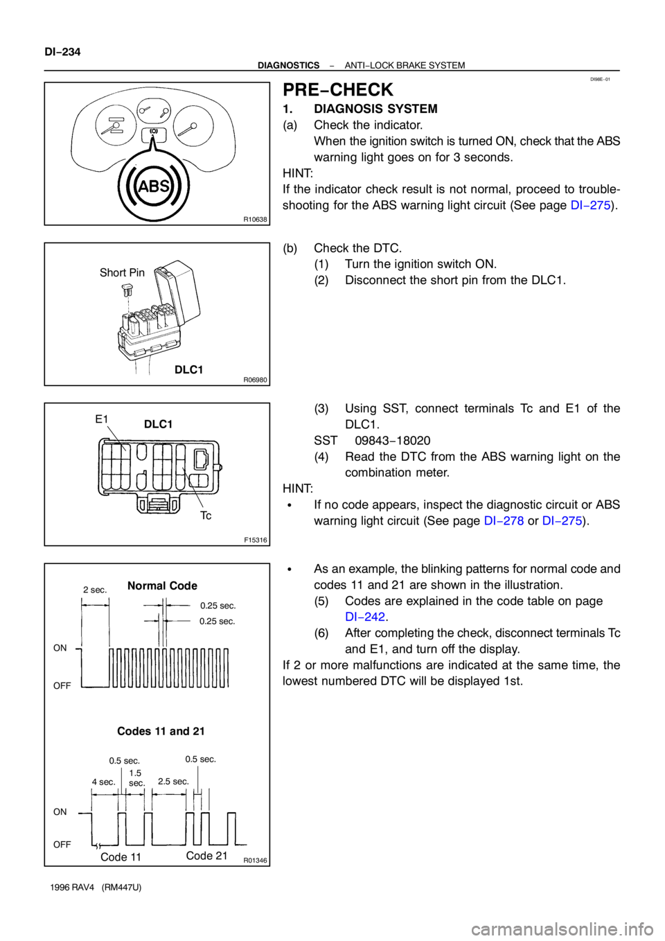
(a) Check the indicator.
When the ignition switch is turned ON, check that the ABS
warning light goes on for 3 seconds.
HINT:
If the indicator check result is not normal, proceed to trouble-
shooting for the ABS warning light circuit (See page DI−275).
(b) Check the DTC.
(1) Turn the ignition switch ON.
(2) Disconnect the short pin from the DLC1.
(3) Using SST, connect terminals Tc and E1 of the
DLC1.
SST 09843−18020
(4) Read the DTC from the ABS warning light on the
combination meter.
HINT:
�If no code appears, inspect the diagnostic circuit or ABS
warning light circuit (See page DI−278 or DI−275).
�As an example, the blinking patterns for normal code and
codes 11 and 21 are shown in the illustration.
(5) Codes are explained in the code table on page
DI−242.
(6) After completing the check, disconnect terminals Tc
and E1, and turn off the display.
If 2 or more malfunctions are indicated at the same time, the
lowest numbered DTC will be displayed 1st.
Page 555 of 1354

BR3890
R06980
Short Pin
DLC1
N09348
Interface Box
Harness VehicleTOYOTA
Tester Hand−held
TOYOTA Break−out−box
− DIAGNOSTICSANTI−LOCK BRAKE SYSTEM
DI−235
1996 RAV4 (RM447U)
(c) Clear the DTC.
(1) Using SST, connect terminals Tc and E1 of the
DLC1.
SST 09843−18020
(2) Disconnect the short pin from the DLC1.
(3) Turn the ignition switch ON.
(4) Clear the DTC stored in ECU by depressing the
brake pedal 8 or more times within 3 seconds (4WD
models) or 5 seconds (2WD models).
(5) Check that the warning light shows the normal
code.
(6) Remove the SST from the terminals of the DLC1.
SST 09843−18020
(7) Connect the short pin to the DLC1.
HINT:
4WD vehicles:
Cancellation can also be done by removing the ECU−B fuse,
but in this case, other memory systems will also canlelled out.
(d) Using TOYOTA break−out−box and TOYOTA hand−held
tester, measure the ECU terminal values.
(1) Turn the ignition switch OFF.
(2) Hook up the TOYOTA hand−held tester and TOYO-
TA break−out−box to the vehicle.
(3) Turn the ignition switch ON.
(4) Read the ECU input / output values by following the
prompts on the tester screen.
HINT:
TOYOTA hand−held tester has a ”Snapshot” function. This re-
cords the measured values and is effective in the diagnosis of
intermittent problems. Please refer to the TOYOTA hand−held
tester / TOYOTA break−out−box operators manual for further
details.
Page 556 of 1354
F15316
E1
TsTc DLC1
BR3904
0.13 sec. 0.13 sec.
ON
OFF
BR3893
72 67
ON
OFF
0.5 sec. 0.5 sec. 0.5 sec. 0.5 sec.1.5 sec.
2.5 sec.4 sec.
Repeat Malfunction Code (Example Code 72, 76) DI−236
− DIAGNOSTICSANTI−LOCK BRAKE SYSTEM
1996 RAV4 (RM447U)
2. SPEED SENSOR SIGNAL CHECK
(a) Check the speed sensor signal.
(1) Turn the ignition switch OFF.
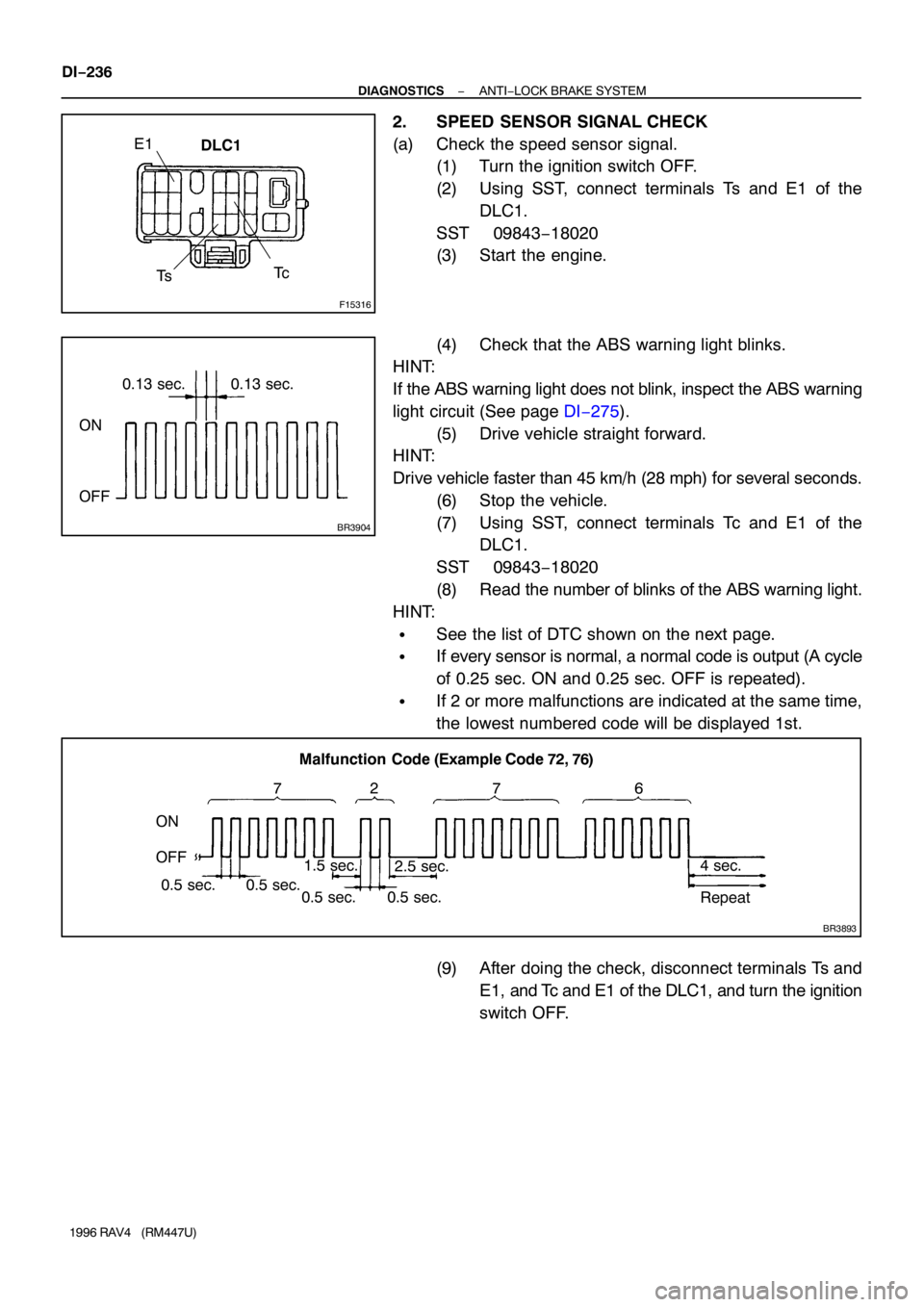
(2) Using SST, connect terminals Ts and E1 of the
DLC1.
SST 09843−18020
(3) Start the engine.
(4) Check that the ABS warning light blinks.
HINT:
If the ABS warning light does not blink, inspect the ABS warning
light circuit (See page DI−275).
(5) Drive vehicle straight forward.
HINT:
Drive vehicle faster than 45 km/h (28 mph) for several seconds.
(6) Stop the vehicle.
(7) Using SST, connect terminals Tc and E1 of the
DLC1.
SST 09843−18020
(8) Read the number of blinks of the ABS warning light.
HINT:
�See the list of DTC shown on the next page.
�If every sensor is normal, a normal code is output (A cycle
of 0.25 sec. ON and 0.25 sec. OFF is repeated).
�If 2 or more malfunctions are indicated at the same time,
the lowest numbered code will be displayed 1st.
(9) After doing the check, disconnect terminals Ts and
E1, and Tc and E1 of the DLC1, and turn the ignition
switch OFF.
Page 567 of 1354
W01937
2
29 10
6 WA8
A9
A9
A8A9
A7 A7
2 25
4 L
R 2
6
A9 A8A84
3
1
A17
A16 A16
A17 A17 A16
*
1*2
15 8
18 5
11 16
98 3
5 A7
A7 EA
EBA71
W−B ALTW−BR−B
R−W
R−L
ABS ActuatorABS ECU Solenoid
RelayABS ECU
MR
R−*1
R+*2
SR
AST
MT BatteryW−R
A17
A17A16
A16 W−BW−BW−R
W−R
ABS1
W−B
ABS Control Relay
Motor
Relay
DLC1
*
1: 2WD Models
*2: 4WD Models
F7
Fusible
Link
Block
G−W
L−O R/B
No. 24 7
− DIAGNOSTICSANTI−LOCK BRAKE SYSTEM
DI−247
1996 RAV4 (RM447U)
WIRING DIAGRAM
Page 571 of 1354
W01937
2
29 10
6 WA8
A9
A9
A8A9
A7 A7
2 25
4 L
R 2
6
A9 A8A84
3
1
A17
A16 A16
A17 A17 A16
*
1*2
15 8
18 5
11 16
98 3
5 A7
A7 EA
EBA71
W−B ALTW−BR−B
R−W
R−L
ABS ActuatorABS ECU Solenoid
RelayABS ECU
MR
R−*1
R+*2
SR
AST
MT BatteryW−R
A17
A17A16
A16 W−BW−BW−R
W−R
ABS1
W−B
ABS Control Relay
Motor
Relay
DLC1
*
1: 2WD Models
*2: 4WD Models
F7
Fusible
Link
Block
G−W
L−O R/B
No. 24 7
− DIAGNOSTICSANTI−LOCK BRAKE SYSTEM
DI−251
1996 RAV4 (RM447U)
WIRING DIAGRAM
Page 589 of 1354
W01937
2
29 10
6 WA8
A9
A9
A8A9
A7 A7
2 25
4 L
R 2
6
A9 A8A84
3
1
A17
A16 A16
A17 A17 A16
*
1*2
15 8
18 5
11 16
98 3
5 A7
A7 EA
EBA71
W−B ALTW−BR−B
R−W
R−L
ABS ActuatorABS ECU Solenoid
RelayABS ECU
MR
R−*1
R+*2
SR
AST
MT BatteryW−R
A17
A17A16
A16 W−BW−BW−R
W−R
ABS1
W−B
ABS Control Relay
Motor
Relay
DLC1
*
1: 2WD Models
*2: 4WD Models
F7
Fusible
Link
Block
G−W
L−O R/B
No. 24 7
− DIAGNOSTICSANTI−LOCK BRAKE SYSTEM
DI−269
1996 RAV4 (RM447U)
DTC 51 ABS Pump Motor Lock
CIRCUIT DESCRIPTION
DTC No.DTC Detecting ConditionTrouble Area
51Pump motor is not operating normally during initial check�ABS pump motor
Fail safe function:
If trouble occurs in the ABS pump motor, the ECU cuts off current to the ABS control (solenoid) relay and
prohibits ABS control.
WIRING DIAGRAM
DI41S−03
Page 591 of 1354
− DIAGNOSTICSANTI−LOCK BRAKE SYSTEM
DI−271
1996 RAV4 (RM447U)
INSPECTION PROCEDURE
1 Is DTC output?
Check DTC on page DI−234.
YES Repair circuit indicated by code output.
NO
2 Is normal code displayed?
YES Check ABS solenoid relay. Check for short in
harness and connector between ABS solenoid
relay and DLC1 (See page IN−30).
NO
3 Is ABS warning light go off?
YES Check for open or short in harness and connec-
tor between ECU−IG Fuse and ECU (See page
IN−30).
NO
4 Check battery positive voltage.
PREPARATION:
Start the engine.
CHECK:
Check the battery positive voltage.
OK:
Voltage: 10 − 16 V
NG Check and repair charging system.
OK