Page 300 of 1354
CO0BG−02
S01613
P15462
P15546
1
3
2
P15463
Disconnect
− COOLINGWATER PUMP
CO−5
1996 RAV4 (RM447U)
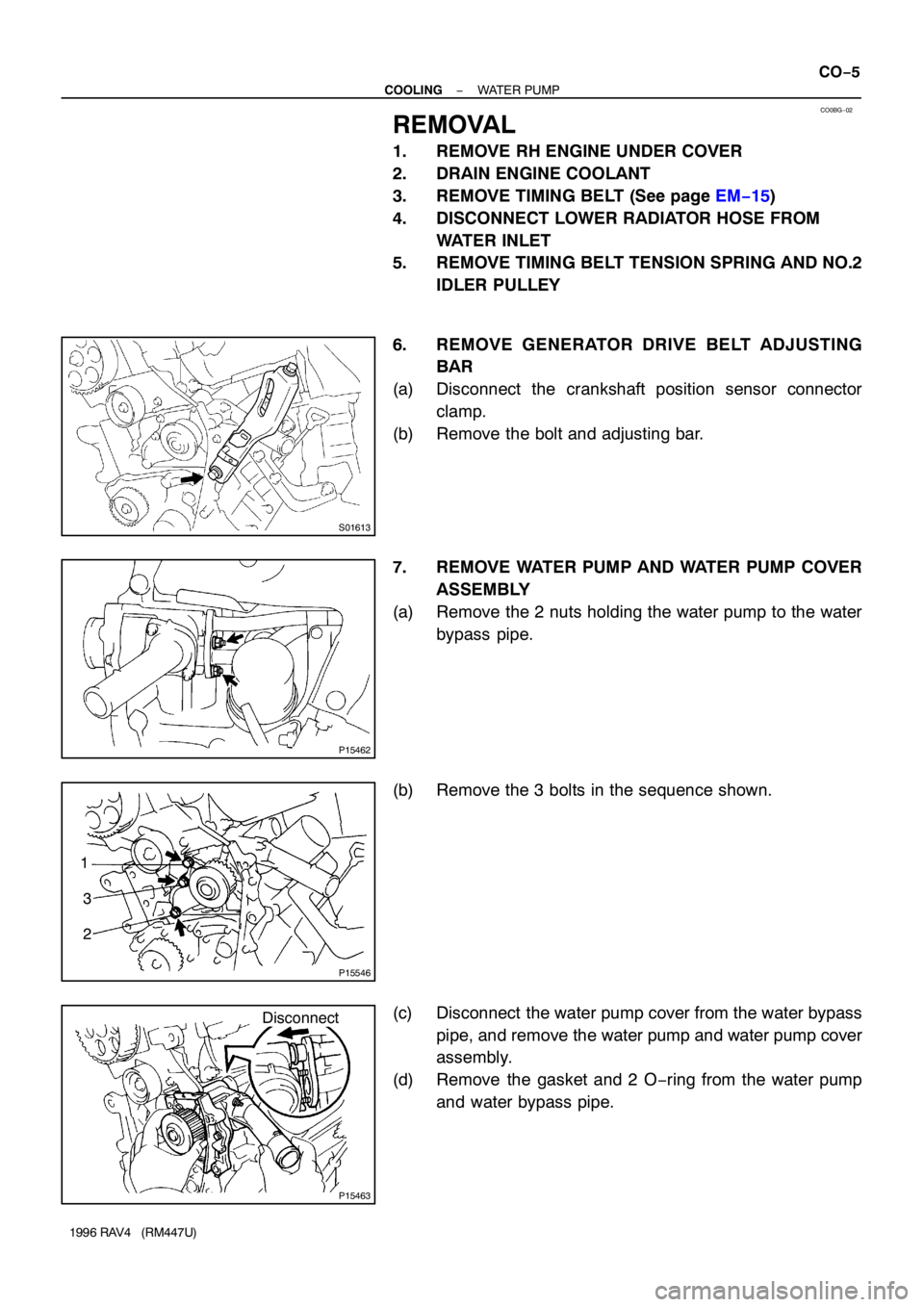
REMOVAL
1. REMOVE RH ENGINE UNDER COVER
2. DRAIN ENGINE COOLANT
3. REMOVE TIMING BELT (See page EM−15)
4. DISCONNECT LOWER RADIATOR HOSE FROM
WATER INLET
5. REMOVE TIMING BELT TENSION SPRING AND NO.2
IDLER PULLEY
6. REMOVE GENERATOR DRIVE BELT ADJUSTING
BAR
(a) Disconnect the crankshaft position sensor connector
clamp.
(b) Remove the bolt and adjusting bar.
7. REMOVE WATER PUMP AND WATER PUMP COVER
ASSEMBLY
(a) Remove the 2 nuts holding the water pump to the water
bypass pipe.
(b) Remove the 3 bolts in the sequence shown.
(c) Disconnect the water pump cover from the water bypass
pipe, and remove the water pump and water pump cover
assembly.
(d) Remove the gasket and 2 O−ring from the water pump
and water bypass pipe.
Page 303 of 1354

CO0BI−03
P13480
New O−Ring
New Gasket
P15547
New O−Ring
P15464
Connect
Z16489
3
1
2 CO−8
− COOLINGWATER PUMP
1996 RAV4 (RM447U)
INSTALLATION
1. INSTALL WATER PUMP TO WATER PUMP COVER
Install a new gasket and the water pump with the 3 bolts.
Torque: 8.8 N·m (90 kgf·cm, 78 in.·lbf)
2. INSTALL WATER PUMP AND WATER PUMP COVER
ASSEMBLY
(a) Install new O−ring and gasket to water pump cover.
(b) Install a new O−ring to the water bypass pipe.
(c) Apply soapy water to the O−ring on the water bypass
pipe.
(d) Connect the water pump cover to the water bypass pipe.
Do not install the nuts yet.
(e) Install the water pump with the 3 bolts. Tighten the bolts
in the sequence shown.
Torque: 8.8 N·m (90 kgf·cm, 78 in.·lbf)
(f) Install the 2 nuts holding the water pump cover to the wa-
ter bypass pipe.
Torque: 9.3 N·m (95 kgf·cm, 82 in.·lbf)
3. INSTALL GENERATOR DRIVE BELT ADJUSTING BAR
(a) Install the adjusting bar with the bolt.
Torque: 27 N·m (275 kgf·cm, 20 ft·lbf)
(b) Connect the crankshaft position sensor connector clamp.
4. INSTALL NO.2 IDLER PULLEY AND TIMING BELT
TENSION SPRING
5. CONNECT LOWER RADIATOR HOSE
6. INSTALL TIMING BELT (See page EM−20)
7. FILL WITH ENGINE COOLANT
8. START ENGINE AND CHECK FOR COOLANT LEAKS
9. INSTALL RH ENGINE UNDER COVER
Page 309 of 1354

CO0BO−02
Z00570
Radiator Cap Tester
Radiator Cap30° or More
S01265
Radiator Cap Tester CO−14
− COOLINGRADIATOR
1996 RAV4 (RM447U)
ON−VEHICLE INSPECTION
1. REMOVE RADIATOR CAP
CAUTION:
To avoid the danger of being burned, do not remove the ra-
diator cap while the engine and radiator are still hot, as fluid
and steam can be blown out under pressure.
2. INSPECT RADIATOR CAP
NOTICE:
�If the radiator cap has contaminations, always rinse
it with water.
�When performing steps (a) and (b) below, keep the ra-
diator cap tester at an angle of over 30°above the hor-
izontal.
(a) Using a radiator cap tester, slowly pump the tester and
check that air is coming from the vacuum valve.
Pump speed:
1 push/(3 seconds or more)
NOTICE:
Push the pump at a constant speed.
If air is not coming from the vacuum valve, replace the radiator
cap.
(b) Pump the tester and measure the relief valve opening
pressure.
Pump speed:
1 push within 1 second
NOTICE:
This pump speed is for the first pump only (in order to close
the vacuum valve). After this, the pump speed can be re-
duced.
Standard opening pressure:
74 − 103 kPa (0.75 − 1.05 kgf/cm
2, 10.7 − 14.9 psi)
Minimum opening pressure:
59 kPa (0.6 kgf/cm
2, 8.5 psi)
HINT:
Use the tester’s maximum reading as the opening pressure.
If the opening pressure is less than minimum, replace the radia-
tor cap.
3. INSPECT COOLING SYSTEM FOR LEAKS
(a) Fill the radiator with coolant and attach a radiator cap tes-
ter.
(b) Warm up the engine.
(c) Pump it to 118kPa (1.2 kgf/cm
2, 17.1 psi), and check that
the pressure does not drop.
If the pressure drops, check the hoses, radiator or water pump
for leaks. If no external leaks are found, check the heater core,
cylinder block and cylinder head.
4. REINSTALL RADIATOR CAP
Page 310 of 1354
CO0BP−02
S01819
Lower Radiator
Hose
No.2 Cooling
Fan Connector
(w/ A/C)
Radiator
Assembly Upper Radiator
Support
ECT Switch
ConnectorRadiator
Upper Radiator
SupportNo.1 Cooling FanNo.2 Cooling Fan
(w/ A/C)
Radiator Cap
Upper Radiator Hose
Engine Wire
Radiator Reservoir Hose
A/T Oil Cooler Hose
� O−Ring
No.1 Cooling
Fan Connector Lower Radiator
Support Cooler Condenser
RH Engine
Under Cover
LH Engine
Under CoverLH Engine
Under Cover
� Non−reusable partM/TA/TDrain Plug
− COOLINGRADIATOR
CO−15
1996 RAV4 (RM447U)
COMPONENTS
Page 311 of 1354
CO0BQ−03
S01355
S01278
w/ A/C
S01293
CO−16
− COOLINGRADIATOR
1996 RAV4 (RM447U)
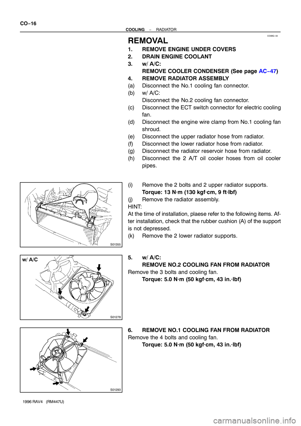
REMOVAL
1. REMOVE ENGINE UNDER COVERS
2. DRAIN ENGINE COOLANT
3. w/ A/C:
REMOVE COOLER CONDENSER (See page AC−47)
4. REMOVE RADIATOR ASSEMBLY
(a) Disconnect the No.1 cooling fan connector.
(b) w/ A/C:
Disconnect the No.2 cooling fan connector.
(c) Disconnect the ECT switch connector for electric cooling
fan.
(d) Disconnect the engine wire clamp from No.1 cooling fan
shroud.
(e) Disconnect the upper radiator hose from radiator.
(f) Disconnect the lower radiator hose from radiator.
(g) Disconnect the radiator reservoir hose from radiator.
(h) Disconnect the 2 A/T oil cooler hoses from oil cooler
pipes.
(i) Remove the 2 bolts and 2 upper radiator supports.
Torque: 13 N·m (130 kgf·cm, 9 ft·lbf)
(j) Remove the radiator assembly.
HINT:
At the time of installation, plaese refer to the following items. Af-
ter installation, check that the rubber cushion (A) of the support
is not depressed.
(k) Remove the 2 lower radiator supports.
5. w/ A/C:
REMOVE NO.2 COOLING FAN FROM RADIATOR
Remove the 3 bolts and cooling fan.
Torque: 5.0 N·m (50 kgf·cm, 43 in.·lbf)
6. REMOVE NO.1 COOLING FAN FROM RADIATOR
Remove the 4 bolts and cooling fan.
Torque: 5.0 N·m (50 kgf·cm, 43 in.·lbf)
Page 314 of 1354
CO0BT−02
S01818
Radiator
No.1 Cooling Fan Lower Radiator Hose
No.2 Cooling
Fan Connector
(w/ A/C)
Upper Radiator
Support
Radiator Cap
Upper Radiator Hose
Engine Wire
Radiator Reservoir Hose
A/T Oil Cooler Hose
Drain Plug
� O−Ring
LH Engine
Under Cover ECT Switch
Connector
Radiator
Assembly
Cooler Condenser
Lower Radiator
Support
No.1 Cooling
Fan Connector
RH Engine
Under Cover
� Non−reusable PartA/T
M/TUpper Radiator
Support
LH Engine
Under Cover NO.1 COOLING FAN
− COOLINGELECTRIC COOLING FAN
CO−19
1996 RAV4 (RM447U)
COMPONENTS
Page 700 of 1354

S01823
Oxygen Sensor
(Bank 1 Sensor 1)
Oxygen Sensor (Bank 1 Sensor 2)
P03152
S01368
S01365
S01594
EM−34
− ENGINE MECHANICALCYLINDER HEAD
1996 RAV4 (RM447U)
10. REMOVE OXYGEN SENSOR (BANK 1 SENSOR 1)
FROM EXHAUST MANIFOLD
11. REMOVE OXYGEN SENSOR (BANK 1 SENSOR 2)
FROM FRONT TWC
12. SEPARATE EXHAUST MANIFORD AND FRON TWC
(a) Remove the 5 bolts and lower manifold heat insulator.
(b) Remove the 8 bolts and 2 TWC heat insulators.
(c) Remove the 3 bolts, 2 nuts, TWC, gasket retainer and
cushion.
13. DISCONNECT OIL PRESSURE SWITCH CONNECTOR
14. REMOVE WATER OUTLET
(a) Disconnect the ECT sensor connector.
(b) Disconnect the ECT sender gauge connector.
(c) Disconnect the radiator hose from the water outlet.
(d) Disconnect the water bypass pipe hose from the water
outlet.
(e) Disconnect the heater water hose from the water outlet.
(f) Remove the 2 nuts, water outlet and gasket.
15. REMOVE WATER BYPASS PIPE
(a) Remove the bolt, 2 nuts and oil cooler heat protector.
(b) Disconnect the IAC valve water bypass hose from the wa-
ter bypass pipe.
(c) Disconnect the heater water hose from the water bypass
pipe.
(d) Disconnect the 2 oil cooler water bypass hoses from the
oil cooler.
(e) Remove the nut and disconnect the wire protector.
(f) Remove the 2 bolts and 2 nuts.
(g) Disconnect the water bypass pipe from the water pump
cover, and remove the water bypass pipe.
(h) Remove the gasket and O−ring.
16. REMOVE THROTTLE BODY (See page SF−30)
Page 728 of 1354
S01560
(1)
(2)
(3)
P15451
ConnectNew
New
Gasket
O−Ring
S01594
S01368
EM−62
− ENGINE MECHANICALCYLINDER HEAD
1996 RAV4 (RM447U)
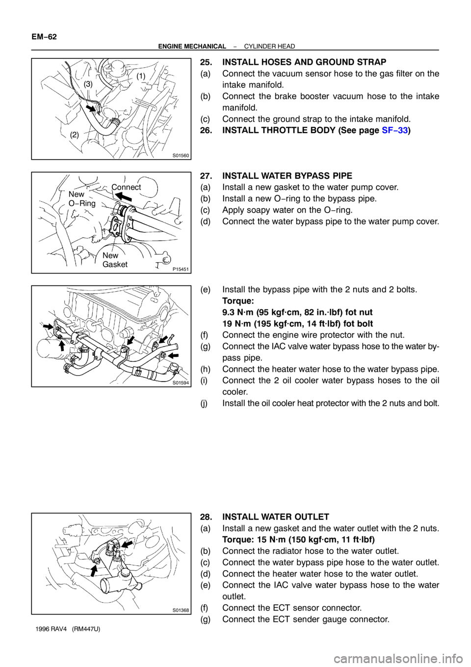
25. INSTALL HOSES AND GROUND STRAP
(a) Connect the vacuum sensor hose to the gas filter on the
intake manifold.
(b) Connect the brake booster vacuum hose to the intake
manifold.
(c) Connect the ground strap to the intake manifold.
26. INSTALL THROTTLE BODY (See page SF−33)
27. INSTALL WATER BYPASS PIPE
(a) Install a new gasket to the water pump cover.
(b) Install a new O−ring to the bypass pipe.
(c) Apply soapy water on the O−ring.
(d) Connect the water bypass pipe to the water pump cover.
(e) Install the bypass pipe with the 2 nuts and 2 bolts.
Torque:
9.3 N·m (95 kgf·cm, 82 in.·lbf) fot nut
19 N·m (195 kgf·cm, 14 ft·lbf) fot bolt
(f) Connect the engine wire protector with the nut.
(g) Connect the IAC valve water bypass hose to the water by-
pass pipe.
(h) Connect the heater water hose to the water bypass pipe.
(i) Connect the 2 oil cooler water bypass hoses to the oil
cooler.
(j) Install the oil cooler heat protector with the 2 nuts and bolt.
28. INSTALL WATER OUTLET
(a) Install a new gasket and the water outlet with the 2 nuts.
Torque: 15 N·m (150 kgf·cm, 11 ft·lbf)
(b) Connect the radiator hose to the water outlet.
(c) Connect the water bypass pipe hose to the water outlet.
(d) Connect the heater water hose to the water outlet.
(e) Connect the IAC valve water bypass hose to the water
outlet.
(f) Connect the ECT sensor connector.
(g) Connect the ECT sender gauge connector.