Page 669 of 1354

EM0EH−03
S01361
Compression
Gauge
− ENGINE MECHANICALCOMPRESSION
EM−3
1996 RAV4 (RM447U)
COMPRESSION
INSPECTION
HINT:
If there is lack of power, excessive oil consumption or poor fuel
economy, measure the compression pressure.
1. WARM UP AND STOP ENGINE
Allow the engine to warm up to normal operating temperature.
2. DISCONNECT DISTRIBUTOR CONNECTOR
3. DISCONNECT HIGH−TENSION CORDS FROM SPARK
PLUGS AND IGNITION COIL
4. REMOVE SPARK PLUGS
5. CHECK CYLINDER COMPRESSION PRESSURE
(a) Insert a compression gauge into the spark plug hole.
(b) Fully open the throttle.
(c) While cranking the engine, measure the compression
pressure.
HINT:
Always use a fully charged battery to obtain engine speed of
250 rpm or more.
(d) Repeat steps (a) through (c) for each cylinder.
NOTICE:
This measurement must be done in as short a time as pos-
sible.
Compression pressure:
1,275 kPa (13.0 kgf/cm
2, 185 psi) or more
Minimum pressure: 932 kPa (9.5 kgf/cm
2, 135 psi)
Difference between each cylinder:
98 kPa (1.0 kgf/cm
2, 14 psi) or less
(e) If the cylinder compression in one or more cylinders is low,
pour a small amount of engine oil into the cylinder through
the spark plug hole and repeat steps (a) through (c) for
cylinders with low compression.
�If adding oil helps the compression, it is likely that
the piston rings and/or cylinder bore are worn or
damaged.
�If pressure stays low, a valve may be sticking or
seating is improper, or there may be leakage past
the gasket.
6. REINSTALL SPARK PLUGS
7. RECONNECT HIGH−TENSION CORDS TO SPARK
PLUGS AND IGNITION COIL
Page 701 of 1354

S01560
(3)(1)
(2)
S01806
S01644
S01791
− ENGINE MECHANICALCYLINDER HEAD
EM−35
1996 RAV4 (RM447U)
17. DISCONNECT HOSES AND GROUND STRAP
(a) Disconnect the vacuum sensor hose from the gas filter on
intake manifold.
(b) Disconnect the brake booster vacuum hose from the in-
take manifold.
(c) Disconnect the ground strap from the intake manifold.
18. DISCONNECT FUEL INLET HOSE FROM FUEL FIL-
TER
Remove the union bolt and 2 gaskets, and disconnect the inlet
hose from the fuel filter.
19. REMOVE EGR VALVE AND VACUUM MODULATOR
(a) Disconnect the 2 vacuum hoses from the VSV for the
EGR.
(b) Disconnect the vacuum modulator from the clamp on the
intake manifold.
(c) Loosen the union nut of the EGR pipe, and remove the 2
nuts, the EGR valve, vacuum modulator, vacuum hoses
assembly and gasket.
20. REMOVE INTAKE MANIFOLD STAY
Remove the 2 bolts and intake manifold stay.
21. A/T only:
DISCONENCT A/T THROTTLE CONTROL CABEL
FROM INTAKE MANIFORD
Disconnect the control cable from the clamp on the rear side of
the intake manifold.
22. DISCONNECT PS IDLE−UP AIR HOSES FROM AIR
TUBE
23. DISCONNECT KNOCK SENSOR CONNECTOR
24. DISCONNECT GROUND CABLE
Remove the bolt, and disconnect the ground cable from the in-
take manifold.
25. REMOVE VSV FOR EGR (See page SF−42)
26. REMOVE CYLINDER HEAD COVER
(a) Remove the 2 bolts and accelerator cable bracket.
(b) Disconnect the PCV hose from the intake manifold.
Page 727 of 1354

S01791
S01644
S01806
− ENGINE MECHANICALCYLINDER HEAD
EM−61
1996 RAV4 (RM447U)
(i) Connect the PCV hose to the intake manifold.
(j) Install the accelerator cable bracket with the 2 bolts.
17. INSTALL VSV FOR EGR (See page SF−42)
18. CONNECT GROUND CABLE
Connect the ground cable to the intake manifold with the bolt.
19. CONNECT KNOCK SENSOR CONNECTOR
20. CONNECT PS IDLE−UP AIR HOSES TO AIR TUBE
21. A/T only:
CONNECT A/T THROTTLE CONTROL CABLE TO IN-
TAKE MANIFOLD
Connect the control cable to the clamp on the rear side of the
intake manifold.
22. INSTALL INTAKE MANIFOLD STAY
Install the intake manifold stay with the 2 bolts.
Torque: 42 N·m (425 kgf·cm, 31 ft·lbf)
23. INSTALL EGR VALVE AND VACUUM MODULATOR
(a) Install a new gasket and the EGR valve with the union nut
and 2 nuts.
Torque:
13 N·m (130 kgf·cm, 9 ft·lbf) for nut
59 N·m (600 kgf·cm, 43 ft·lbf) for union nut
(b) Install the vacuum modulator to the clamp on the intake
manifold.
(c) Connect the 2 vacuum hoses to the VSV for the EGR.
24. CONNECT FUEL INLET HOSE TO FUEL FILTER
Connect the inlet hose with 2 new gaskets and the union bolt.
Torque: 29 N·m (300 kgf·cm, 22 ft·lbf)
Page 731 of 1354
EM0EV−02
A04063
N·m (kgf·cm, ft·lbf) : Specified torque
� Non−reusable part
29 (300, 22)
Hold Down ClampHold Down Clamp
BatteryEngine Hood
Battery Tray
Lower Radiator
HosePS Pump
w/ BracketCharcoal Canister
Battery Tray
IAT Sensor ConnectorAir Cleaner Cap
� Gasket
� Gasket
Fuel Inlet Hose
Fuel Filter
Water Inlet
Upper Radiator
Hose
Heater Hose
PS Pump Drive Belt
Generator Drive
Belt
Accelerator Cable
Generator
Generator Drive Belt
Adjusting Bar
Air Filter
EVAP VSV Connector
Air Cleaner Case
Radiator
Reservoir
Relay Block No. 2
Upper Cover
Relay Block No. 2
Wire Harness
A/C Compressor
Type B Type A
Type B Type A
− ENGINE MECHANICALENGINE UNIT
EM−65
1996 RAV4 (RM447U)
ENGINE UNIT
COMPONENTS
Page 734 of 1354

EM1BA−02
S01374
Cover
Connector EM−68
− ENGINE MECHANICALENGINE UNIT
1996 RAV4 (RM447U)
REMOVAL
1. REMOVE BATTERY
2. REMOVE ENGINE HOOD
3. REMOVE ENGINE UNDER COVERS
4. DRAIN ENGINE COOLANT
5. DRAIN ENGINE OIL
6. DRAIN TRANSAXLE OIL
7. REMOVE AIR CLEANER CAP AND CASE
8. DISCONNECT ACCELERATOR CABLE FROM
THROTTLE BODY, CABLE BRACKET AND CLAMPS
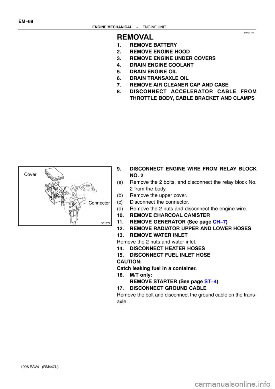
9. DISCONNECT ENGINE WIRE FROM RELAY BLOCK
NO. 2
(a) Remove the 2 bolts, and disconnect the relay block No.
2 from the body.
(b) Remove the upper cover.
(c) Disconnect the connector.
(d) Remove the 2 nuts and disconnect the engine wire.
10. REMOVE CHARCOAL CANISTER
11. REMOVE GENERATOR (See page CH−7)
12. REMOVE RADIATOR UPPER AND LOWER HOSES
13. REMOVE WATER INLET
Remove the 2 nuts and water inlet.
14. DISCONNECT HEATER HOSES
15. DISCONNECT FUEL INLET HOSE
CAUTION:
Catch leaking fuel in a container.
16. M/T only:
REMOVE STARTER (See page ST−4)
17. DISCONNECT GROUND CABLE
Remove the bolt and disconnect the ground cable on the trans-
axle.
Page 744 of 1354

S01797
M/T
A/T
S01785
A/T Only
S01351
M/T Only
Back−up Light
Connector EM−78
− ENGINE MECHANICALENGINE UNIT
1996 RAV4 (RM447U)
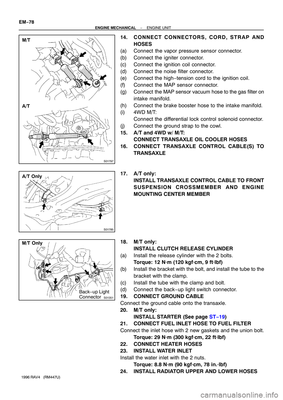
14. CONNECT CONNECTORS, CORD, STRAP AND
HOSES
(a) Connect the vapor pressure sensor connector.
(b) Connect the igniter connector.
(c) Connect the ignition coil connector.
(d) Connect the noise filter connector.
(e) Connect the high−tension cord to the ignition coil.
(f) Connect the MAP sensor connector.
(g) Connect the MAP sensor vacuum hose to the gas filter on
intake manifold.
(h) Connect the brake booster hose to the intake manifold.
(i) 4WD M/T:
Connect the differential lock control solenoid connector.
(j) Connect the ground strap to the cowl.
15. A/T and 4WD w/ M/T:
CONNECT TRANSAXLE OIL COOLER HOSES
16. CONNECT TRANSAXLE CONTROL CABLE(S) TO
TRANSAXLE
17. A/T only:
INSTALL TRANSAXLE CONTROL CABLE TO FRONT
SUSPENSION CROSSMEMBER AND ENGINE
MOUNTING CENTER MEMBER
18. M/T only:
INSTALL CLUTCH RELEASE CYLINDER
(a) Install the release cylinder with the 2 bolts.
Torque: 12 N·m (120 kgf·cm, 9 ft·lbf)
(b) Install the bracket with the bolt, and install the tube to the
bracket with the clamp.
(c) Install the tube with the clamp and bolt.
(d) Connect the back−up light switch connector.
19. CONNECT GROUND CABLE
Connect the ground cable onto the transaxle.
20. M/T only:
INSTALL STARTER (See page ST−19)
21. CONNECT FUEL INLET HOSE TO FUEL FILTER
Connect the inlet hose with 2 new gaskets and the union bolt.
Torque: 29 N·m (300 kgf·cm, 22 ft·lbf)
22. CONNECT HEATER HOSES
23. INSTALL WATER INLET
Install the water inlet with the 2 nuts.
Torque: 8.8 N·m (90 kgf·cm, 78 in.·lbf)
24. INSTALL RADIATOR UPPER AND LOWER HOSES
Page 785 of 1354
15
ABBREVIATIONS D
ABBREVIATIONS
The following abbreviations are used in this manual.
ABS = Anti-Lock Brake System
A/C = Air Conditioning
A/T = Automatic Transaxle
COMB. = Combination
DIFF. = Differential
ECU = Electronic Control Unit
EGR = Exhaust Gas Recirculation
EVAP = Evaporative Emission
J/B = Junction Block
LH = Left-Hand
M/T = Manual Transaxle
O/D = Overdrive
R/B = Relay Block
RH = Right-Hand
SFI = Sequential Multiport Fuel Injection
SRS = Supplemental Restraint System
SW = Switch
TEMP. = Temperature
VSV = Vacuum Switching Valve
w/ = With
w/o = Without
2WD = Two Wheel Drive
4WD = Four Wheel Drive
* The titles given inside the components are the names of the terminals (terminal codes) and are not
treated as being abbreviations.
Page 786 of 1354

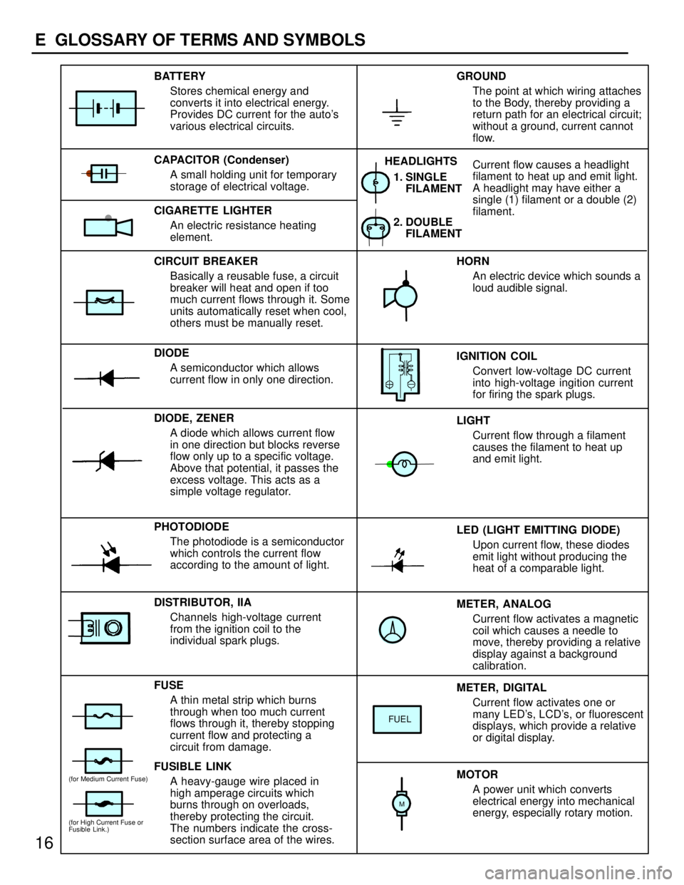
METER, ANALOG
Current flow activates a magnetic
coil which causes a needle to
move, thereby providing a relative
display against a background
calibration. LED (LIGHT EMITTING DIODE)
Upon current flow, these diodes
emit light without producing the
heat of a comparable light. IGNITION COIL
Convert low-voltage DC current
into high-voltage ingition current
for firing the spark plugs. 1. SINGLE
FILAMENT
GROUND
The point at which wiring attaches
to the Body, thereby providing a
return path for an electrical circuit;
without a ground, current cannot
flow.
Current flow causes a headlight
filament to heat up and emit light.
A headlight may have either a
single (1) filament or a double (2)
filament. BATTERY
Stores chemical energy and
converts it into electrical energy.
Provides DC current for the auto's
various electrical circuits.
CAPACITOR (Condenser)
A small holding unit for temporary
storage of electrical voltage.
CIRCUIT BREAKER
Basically a reusable fuse, a circuit
breaker will heat and open if too
much current flows through it. Some
units automatically reset when cool,
others must be manually reset.
DIODE
A semiconductor which allows
current flow in only one direction.
DIODE, ZENER
A diode which allows current flow
in one direction but blocks reverse
flow only up to a specific voltage.
Above that potential, it passes the
excess voltage. This acts as a
simple voltage regulator.
PHOTODIODE
The photodiode is a semiconductor
which controls the current flow
according to the amount of light.
FUSE
A thin metal strip which burns
through when too much current
flows through it, thereby stopping
current flow and protecting a
circuit from damage.
FUSIBLE LINK
A heavy-gauge wire placed in
high amperage circuits which
burns through on overloads,
thereby protecting the circuit.
The numbers indicate the cross-
section surface area of the wires.HORN
An electric device which sounds a
loud audible signal.
LIGHT
Current flow through a filament
causes the filament to heat up
and emit light.
METER, DIGITAL
Current flow activates one or
many LED's, LCD's, or fluorescent
displays, which provide a relative
or digital display.
MOTOR
A power unit which converts
electrical energy into mechanical
energy, especially rotary motion. CIGARETTE LIGHTER
An electric resistance heating
element.
DISTRIBUTOR, IIA
Channels high-voltage current
from the ignition coil to the
individual spark plugs.2. DOUBLE
FILAMENT HEADLIGHTS
FUEL
(for High Current Fuse or
Fusible Link.)
(for Medium Current Fuse)
M
16
E GLOSSARY OF TERMS AND SYMBOLS