Page 551 of 1354
D02310
3
1
54 2
− DIAGNOSTICSAUTOMATIC TRANSAXLE (A540H)
DI−231
1996 RAV4 (RM447U)
3 Check pattern select switch.
PREPARATION:
Remove the pattern select switch.
CHECK:
Measure the resistance between terminals 1 and 3 of the pat-
tern select switch connector when the select switch is set to
PWR and NORM positions.
OK:
PatternResistance
PWR0 Ω (continuity)
NORM∞ Ω (open)
NG Replace pattern select switch.
OK
4 Check harness and connector between battery and pattern select switch, and
pattern select switch and ECM (See page IN−30).
NG Repair or replace harness or connector.
OK
Check and replace ECM.
Page 569 of 1354
F04134
A8A9
A8A9
(+)
(−)
31
3
65 2
1
65 2
− DIAGNOSTICSANTI−LOCK BRAKE SYSTEM
DI−249
1996 RAV4 (RM447U)
3 Check ABS control (solenoid) relay.
CHECK:
Check the continuity between each terminal of the ABS control
(solenoid) relay.
OK:
Terminals A9−1 and A8−3Continuity
(Reference value 80 Ω)
Terminals A9−5 and A9−6Continuity
Terminals A9−2 and A9−5Open
CHECK:
(a) Apply battery voltage between terminals A9−1 and A8−3.
(b) Check the continuity between each terminal of the ABS
control (solenoid) relay.
OK:
Terminals A9−5 and A9−6Open
Terminals A9−2 and A9−5Continuity
NG Replace ABS control relay.
OK
4 Check for open and short in harness and connector between ABS control relay
and ABS ECU (See page IN−30).
NG Repair or replace harness or connector.
OK
If same code is still output after DTC is deleted, check contact condition of each connection. If
connections are normal, ECU may be defective.
Page 573 of 1354
F04137
A8A9
A8A9
(−) (+)1
3 2
42
4
31
− DIAGNOSTICSANTI−LOCK BRAKE SYSTEM
DI−253
1996 RAV4 (RM447U)
3 Check ABS control (motor) relay.
CHECK:
Check the continuity between each terminal of the ABS control
relay.
OK:
Terminals A8−3 and A8−4Continuity
(Reference value 68 Ω)
Terminals A8−1 and A8−2Open
CHECK:
(a) Apply battery voltage between terminals A8−3 and A8−4.
(b) Check the continuity between terminal of the ABS control
relay.
OK:
Terminals A8−1 and A8−2Continuity
NG Replace ABS control relay.
OK
4 Check for open and short in harness and connector between ABS control relay
and ABS ECU (See page IN−30).
NG Repair or replace harness or connector.
OK
If same code is still output after DTC is deleted, check contact condition of each connection. If
connections are normal, ECU may be defective.
Page 583 of 1354
BE6653
W01408
R15782
F15317
ON
2WD Models
IG1
GNDGND
GND (−) (+)
IG1
4WD Models
(−)(+)
GND
− DIAGNOSTICSANTI−LOCK BRAKE SYSTEM
DI−263
1996 RAV4 (RM447U)
INSPECTION PROCEDURE
1 Check battery positive voltage.
OK:
Voltage: 10 − 14 V
NG Check and repair charging system.
OK
2 Check voltage between terminals IG1 and GND of ABS ECU connector.
PREPARATION:
Remove the ABS ECU with connectors still connected.
CHECK:
(a) Turn the ignition switch ON.
(b) Measure the voltage between terminals IG1 and GND of
the ABS ECU connector.
OK:
Voltage: 10 − 14 V
OK Check and replace ABS ECU.
NG
Page 586 of 1354

DI−266
− DIAGNOSTICSANTI−LOCK BRAKE SYSTEM
1996 RAV4 (RM447U)
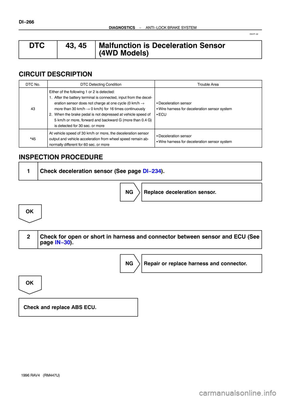
DTC 43, 45 Malfunction is Deceleration Sensor
(4WD Models)
CIRCUIT DESCRIPTION
DTC No.DTC Detecting ConditionTrouble Area
43
Either of the following 1 or 2 is detected:
1. After the battery terminal is connected, input from the decel-
eration sensor does not charge at one cycle (0 km/h →
more than 30 km/h → 0 km/h) for 16 times continuously
2. When the brake pedal is not depressed at vehicle speed of
5 km/h or more, forward and backward G (more than 0.4 G)
is detected for 30 sec. or more
�Deceleration sensor
�Wire harness for deceleration sensor system
�ECU
*45
At vehicle speed of 30 km/h or more, the deceleration sensor
output and vehicle acceleration from wheel speed remain ab-
normally different for 60 sec. or more�Deceleration sensor
�Wire harness for deceleration sensor system
INSPECTION PROCEDURE
1 Check deceleration sensor (See page DI−234).
NG Replace deceleration sensor.
OK
2 Check for open or short in harness and connector between sensor and ECU (See
page IN−30).
NG Repair or replace harness and connector.
OK
Check and replace ABS ECU.
DI41P−02
Page 596 of 1354

R14139
1 2
5 6 3A8
A9
R14140
(−)
(+)1 2
5
6
3A8
A9
R14144
(+) (−)4 5 A8
A9
DI−276
− DIAGNOSTICSANTI−LOCK BRAKE SYSTEM
1996 RAV4 (RM447U)
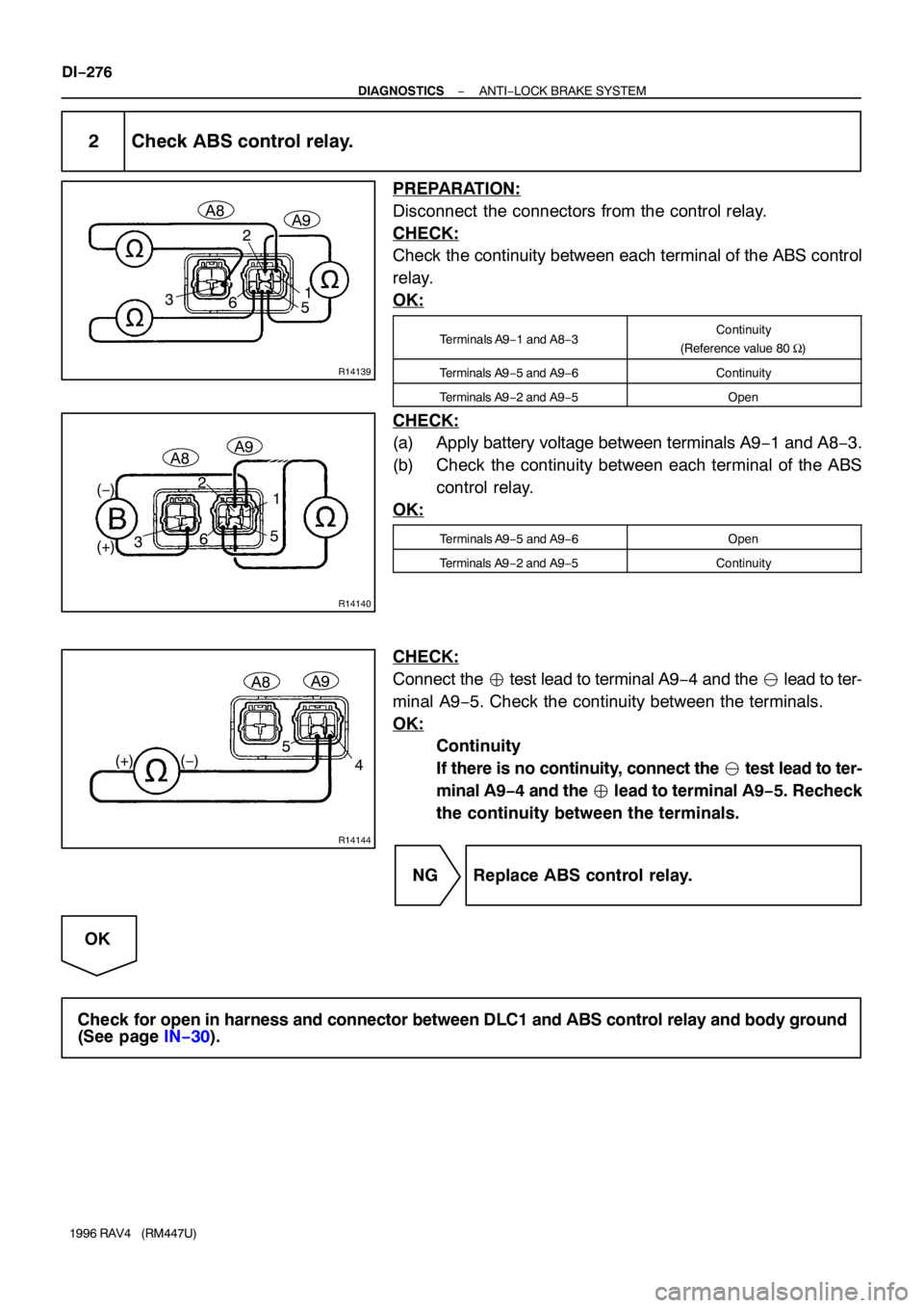
2 Check ABS control relay.
PREPARATION:
Disconnect the connectors from the control relay.
CHECK:
Check the continuity between each terminal of the ABS control
relay.
OK:
Terminals A9−1 and A8−3Continuity
(Reference value 80 Ω)
Terminals A9−5 and A9−6Continuity
Terminals A9−2 and A9−5Open
CHECK:
(a) Apply battery voltage between terminals A9−1 and A8−3.
(b) Check the continuity between each terminal of the ABS
control relay.
OK:
Terminals A9−5 and A9−6Open
Terminals A9−2 and A9−5Continuity
CHECK:
Connect the � test lead to terminal A9−4 and the � lead to ter-
minal A9−5. Check the continuity between the terminals.
OK:
Continuity
If there is no continuity, connect the � test lead to ter-
minal A9−4 and the � lead to terminal A9−5. Recheck
the continuity between the terminals.
NG Replace ABS control relay.
OK
Check for open in harness and connector between DLC1 and ABS control relay and body ground
(See page IN−30).
Page 609 of 1354

DI42J−02
DI−332
− DIAGNOSTICSCRUISE CONTROL SYSTEM
1996 RAV4 (RM447U)
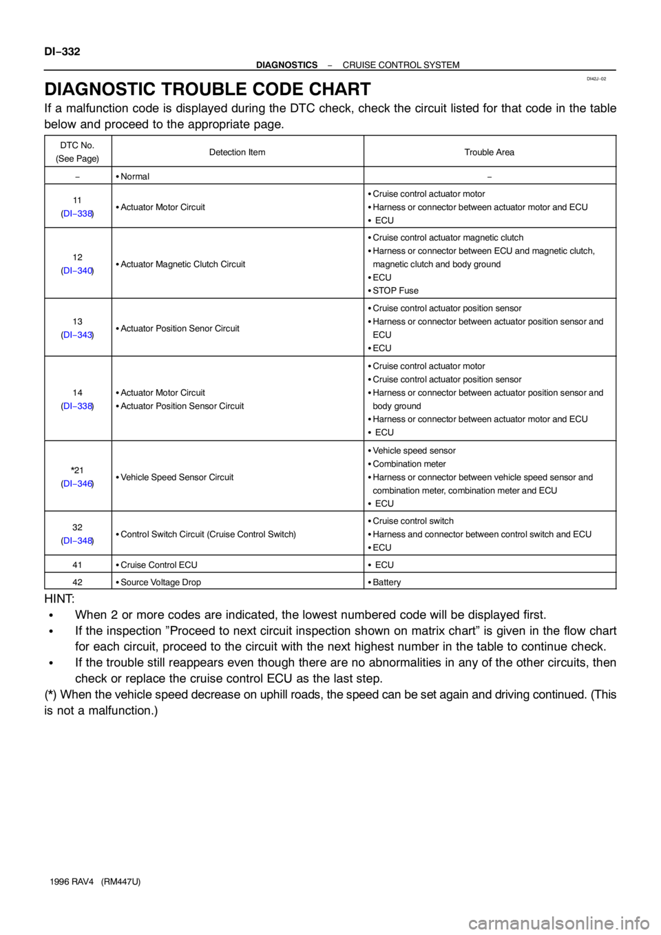
DIAGNOSTIC TROUBLE CODE CHART
If a malfunction code is displayed during the DTC check, check the circuit listed for that code in the table
below and proceed to the appropriate page.
DTC No.
(See Page)Detection ItemTrouble Area
−�Normal−
11
(DI−338)�Actuator Motor Circuit
�Cruise control actuator motor
�Harness or connector between actuator motor and ECU
� ECU
12
(DI−340)�Actuator Magnetic Clutch Circuit
�Cruise control actuator magnetic clutch
�Harness or connector between ECU and magnetic clutch,
magnetic clutch and body ground
�ECU
�STOP Fuse
13
(DI−343)�Actuator Position Senor Circuit
�Cruise control actuator position sensor
�Harness or connector between actuator position sensor and
ECU
�ECU
14
(DI−338)�Actuator Motor Circuit
�Actuator Position Sensor Circuit
�Cruise control actuator motor
�Cruise control actuator position sensor
�Harness or connector between actuator position sensor and
body ground
�Harness or connector between actuator motor and ECU
� ECU
*21
(DI−346)�Vehicle Speed Sensor Circuit
�Vehicle speed sensor
�Combination meter
�Harness or connector between vehicle speed sensor and
combination meter, combination meter and ECU
� ECU
32
(DI−348)�Control Switch Circuit (Cruise Control Switch)
�Cruise control switch
�Harness and connector between control switch and ECU
�ECU
41�Cruise Control ECU� ECU
42�Source Voltage Drop�Battery
HINT:
�When 2 or more codes are indicated, the lowest numbered code will be displayed first.
�If the inspection ”Proceed to next circuit inspection shown on matrix chart” is given in the flow chart
for each circuit, proceed to the circuit with the next highest number in the table to continue check.
�If the trouble still reappears even though there are no abnormalities in any of the other circuits, then
check or replace the cruise control ECU as the last step.
(*) When the vehicle speed decrease on uphill roads, the speed can be set again and driving continued. (This
is not a malfunction.)
Page 616 of 1354

N14648N17426I09111
Acceleration
SideDeceleration
Side
Control
Plate (+)5
4
(−)
− DIAGNOSTICSCRUISE CONTROL SYSTEM
DI−339
1996 RAV4 (RM447U)
INSPECTION PROCEDURE
1 Check actuator motor.
PREPARATION:
(a) Remove cruise control actuator.
(b) Disconnect actuator connector.
CHECK:
(a) Connect positive + lead to terminal 5 and negative − lead
to terminal 4 of actuator connector (Magnetic clutch ON).
NOTICE:
Do not connect the high tension cables to the wrong bat-
tery terminal.
You will damage the cruise control actuator.
(b) When battery positive voltage is applied to each terminal
of actuator connector, check that the control plate moves
smoothly without hesitating.
Moving directionTerminal No. to connect
Acceleration sidePositive + − 6Negative − − 7
Deceleration sidePositive + − 7Negative − − 6
(c) With the motor rotating as in 2., check that the motor is
stopped by limit switches when the control plate moves to
fully opened or fully closed position.
NG Replace actuator assembly.
OK
2 Check harness and connector between cruise control ECU and actuator motor
(See page IN−30).
NG Repair or replace harness or connector.
OK
Proceed to next circuit inspection shown on matrix chart (See page DI−336).
However, when DTC 11, 14 is displayed, check and replace cruise control ECU.