Page 17 of 1354

Q08774
Q08768
D01757
Q08769
C
D
NutAB C
D
A
B
B
B
Nut
Q08770
− AUTOMATIC TRANSAXLE (A241E)AUTOMATIC TRANSAXLE UNIT
AX−17
1996 RAV4 (RM447U)
15. DISCONNECT FOLLOWING CONNECTORS
�Shift solenoid valve SL connector
�Park/neutral position switch connector
�Vehicle speed sensor connector
16. DISCONNECT 2 OIL COOLER HOSES
Loosen the 2 clips and disconnect the 2 oil cooler hoses.
17. REMOVE 2 POWER STEERING GEAR MOUNTING
BOLTS AND NUTS
Torque: 113 N·m (1,150 kgf·cm, 83 ft·lbf)
NOTICE:
Support the power steering gear housing securely.
18. REMOVE FRONT SUSPENSION CROSSMEMBER AS-
SEMBLY WITH STABILIZER BAR
Remove the 10 bolts, 2 nuts and front suspension crossmem-
ber assembly with stabilizer bar.
Torque:
A bolt: 206 N·m (2,100 kgf·cm, 152 ft·lbf)
B bolt: 137 N·m (1,400 kgf·cm, 101 ft·lbf)
C bolt: 35 N·m (360 kgf·cm, 26 ft·lbf)
D bolt: 72 N·m (730 kgf·cm, 53 ft·lbf)
Nut: 73 N·m (740 kgf·cm, 54 ft·lbf)
19. REMOVE STIFFENER PLATE
Remove the 3 bolts and stiffener plate.
Torque: 37 N·m (380 kgf·cm, 27 ft·lbf)
Page 18 of 1354
Z18887
A
A
A
B
Q08772
Q08773
A
B AX−18
− AUTOMATIC TRANSAXLE (A241E)AUTOMATIC TRANSAXLE UNIT
1996 RAV4 (RM447U)
20. REMOVE REAR END PLATE
Remove the 4 bolts and rear end plate.
Torque:
A bolt: 9.0 N·m (95 kgf·cm, 78 in.·lbf)
B bolt: 19 N·m (195 kgf·cm, 14 ft·lbf)
21. REMOVE TORQUE CONVERTER CLUTCH MOUNT-
ING BOLT
Turn the crankshaft to gain access and remove the 6 bolts with
holding the crankshaft pulley set bolt by a wrench.
Torque: 27 N·m (280 kgf·cm, 20 ft·lbf)
HINT:
At the time of installation, please refer to the following item.
First install the gray bolt. Then install 5 black bolts while turning
the crankshaft to grain access.
22. SUPPORT TRANSAXLE WITH A TRANSMISSION
JACK
23. REMOVE TRANSAXLE
Remove the rear side transaxle mouting 2 bolts and transaxle.
Torque:
A bolt: 25 N·m (250 kgf·cm, 18 ft·lbf)
B bolt: 46 N·m (470 kgf·cm, 34 ft·lbf)
Page 19 of 1354
AT3412
AX059−03
− AUTOMATIC TRANSAXLE (A241E)AUTOMATIC TRANSAXLE UNIT
AX−19
1996 RAV4 (RM447U)
INSTALLATION
1. INSTALL TORQUE CONVERTER CLUTCH
Using calipers and a straight edge, measure from the installed
surface to front surface of the transaxle housing.
Correct distance: More than 12.75 mm (0.502 in.)
2. INSTALL TRANSAXLE
Installation is in the reverse order of removal (See page
AX−15).
HINT:
After installation, check and inspect items as follows.
�Fluid level (See page DI−127)
�Front wheel alignment (See page SA−4)
�Road test the vehicle
Page 20 of 1354

AT0953
SST
AX05A−02
AT3306
Hold
Lock
Free
Turn
D00776
AT4184
AX−20
− AUTOMATIC TRANSAXLE (A241E)TORQUE CONVERTER CLUTCH AND DRIVE PLATE
1996 RAV4 (RM447U)
TORQUE CONVERTER CLUTCH
AND DRIVE PLATE
INSPECTION
1. INSPECT ONE−WAY CLUTCH
(a) Install SST into the inner race of the one−way clutch.
SST 09350−32014 (09351−32010)
(b) Install SST so that it fits in the notch of the converter clutch
hub and outer race of the one−way clutch.
SST 09350−32014 (09351−32020)
(c) With the torque converter clutch standing on its side,the
clutch locks when turned counterclockwise, and rotates
freely and smoothly clockwise.
If necessary, clean the converter clutch and retest the clutch.
Replace the converter clutch if the clutch still fails the test.
2. MEASURE DRIVE PLATE RUNOUT AND INSPECT
RING GEAR
Set up a dial indicator, measure the drive plate runout.
Maximum runout: 0.20 mm (0.0079 in.)
If the runout is not within the specification or if the ring gear is
damaged, replace the drive plate. If installing a new drive plate,
note the orientation of spacers and tighten the bolts.
Torque: 83 N·m (850 kgf·cm, 61 ft·lbf)
3. MEASURE TORQUE CONVERTER CLUTCH SLEEVE
RUNOUT
Temporarily mount the torque converter clutch to the drive
plate. Set up a dial indicator, measure the torque converter
clutch sleeve runout.
Maximum runout: 0.30 mm (0.0118 in.)
If the runout is not within the specification, try to correcting by
reorienting the installation of the converter clutch.
Page 21 of 1354
− AUTOMATIC TRANSAXLE (A241E)TORQUE CONVERTER CLUTCH AND DRIVE PLATE
AX−21
1996 RAV4 (RM447U)
HINT:
Mark the position of the torque converter clutch to ensure cor-
rect installation.
Page 445 of 1354

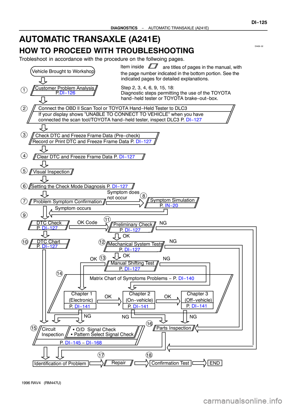
DI409−02
Vehicle Brought to Workshop
P.DI−126
Connect the OBD ll Scan Tool or TOYOTA Hand−Held Tester to DLC3
If your display shows ”UNABLE TO CONNECT TO VEHICLE” when you have
connected the scan tool/TOYOTA hand−held tester, inspect DLC3 P. DI−127
Check DTC and Freeze Frame Data (Pre−check)
Record or Print DTC and Freeze Frame Data P. DI−127
Clear DTC and Freeze Frame Data P. DI−127 Customer Problem Analysis
Visual Inspection
DTC CheckSymptom Simulation Setting the Check Mode Diagnosis P. DI−127
Problem Symptom Confirmation
P. IN−20 Symptom does
not occur
OK Codethe page number indicated in the bottom portion. See the
indicated pages for detailed explanations.
Preliminary Checkare titles of pages in the manual, with Item inside
Mechanical System Tests DTC Chart
Chapter 1
(Electronic)Manual Shifting Test
Matrix Chart of Symptoms Problems − P. DI−140
(On−vehicle)
� Pattern Select Signal Check � O/D Signal Check
InspectionCircuit(Off−vehicle) Chapter 2 Chapter 3
END Repair
Confirmation Test
Identification of ProblemParts Inspection P. DI−127
P. DI−127P. DI−127
P. DI−127
P. DI−127
P. DI−145 − DI−168 P. DI−141 1
2
P. DI−141P. DI−141 3
4
5
6
78
9
1011
12
13
14
16
18 15
17
Symptom occurs
OKNG
OKNG
NG
OK
OK OK
NG
NGNG
Step 2, 3, 4, 6, 9, 15, 18:
Diagnostic steps permitting the use of the TOYOTA
hand−held tester or TOYOTA brake−out−box.
− DIAGNOSTICSAUTOMATIC TRANSAXLE (A241E)
DI−125
1996 RAV4 (RM447U)
AUTOMATIC TRANSAXLE (A241E)
HOW TO PROCEED WITH TROUBLESHOOTING
Trobleshoot in accordance with the procedure on the follwoing pages.
Page 446 of 1354
Brought InInspector ’s
System Check Sheet
Name
Customer ’s NameTransaxle Control
Registration No.
Frame No.
Date VehicleRegistration Year:
Date Problem
Frequency
Problem Occurs Occurred/ /
Odometer Reading
SymptomsIntermittent ( times a day)
Vehicle does not move Any positionContinuous
Particular position) / /km
mile
/ /
Shift point too high or too low No up−shift 1st → 2nd
Lock−up malfunction
Harsh engagement No down−shift
(
3rd → O/D) (
N → D (
2nd → 1st) 2nd → 3rd
3rd → 2nd O/D → 3rd
Slip or shudder
No kick−down
Malfunction code (Code )Any drive position) Lock−up
Others
1st Time
2nd Time(
Indicator LampRemains ON Check ItemMalfunction
Normal
DTC Check
Normal
NormalMalfunction code (Code )
DI40A−01
DI−126
− DIAGNOSTICSAUTOMATIC TRANSAXLE (A241E)
1996 RAV4 (RM447U)
CUSTOMER PROBLEM ANALYSIS CHECK
Page 447 of 1354

DI40B−02
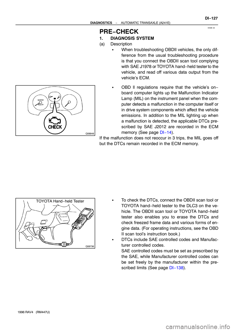
Q08848
Q08736
TOYOTA Hand−held Tester
− DIAGNOSTICSAUTOMATIC TRANSAXLE (A241E)
DI−127
1996 RAV4 (RM447U)
PRE−CHECK
1. DIAGNOSIS SYSTEM
(a) Description
�When troubleshooting OBDII vehicles, the only dif-
ference from the usual troubleshooting procedure
is that you connect the OBDII scan tool complying
with SAE J1978 or TOYOTA hand−held tester to the
vehicle, and read off various data output from the
vehicle’s ECM.
�OBD ll regulations require that the vehicle’s on−
board computer lights up the Malfunction Indicator
Lamp (MIL) on the instrument panel when the com-
puter detects a malfunction in the computer itself or
in drive system components which affect the vehicle
emissions. In addition to the MIL lighting up when
a malfunction is detected, the applicable DTCs pre-
scribed by SAE J2012 are recorded in the ECM
memory (See page DI−14).
If the malfunction does not reoccur in 3 trips, the MIL goes off
but the DTCs remain recorded in the ECM memory.
�To check the DTCs, connect the OBDII scan tool or
TOYOTA hand−held tester to the DLC3 on the ve-
hicle. The OBDII scan tool or TOYOTA hand−held
tester also enables you to erase the DTCs and
check freezed frame data and various forms of en-
gine data. (For operating instructions, see the OBD
II scan tool’s instruction book.)
�DTCs include SAE controlled codes and Manufac-
turer controlled codes.
SAE controlled codes must be set as prescribed by
the SAE, while Manufacturer controlled codes can
be set freely by the manufacturer within the pre-
scribed limits (See page DI−138).