Page 166 of 1354
R00934
Pedal Reverse
Distance
− BRAKEBRAKE PEDAL
BR−7
1996 RAV4 (RM447U)
HINT:
The freeplay to the 1st point of resistance is due to the play be-
tween the clevis and pin. It is 1 − 3 mm (0.04 − 0.12 in.) on the
pedal.
If incorrect, check the stop light switch clearance. If the clear-
ance is OK, then troubleshoot the brake system.
4. CHECK PEDAL RESERVE DISTANCE
(a) Release the parking brake.
(b) With the engine running, depress the pedal and measure
the pedal reserve distance, as shown.
Pedal reserve distance from asphalt sheet at 490 N
(50 kgf, 110.2 lbf): More than 75 mm (2.95 in.)
If the reserve distance is incorrect, troubleshoot the brake sys-
tem.
Page 175 of 1354
BR2237
BR02Q−02
BR2238
GOOD
1st2nd3rdNO GOOD BR−16
− BRAKEBRAKE BOOSTER ASSEMBLY
1996 RAV4 (RM447U)
BRAKE BOOSTER ASSEMBLY
ON−VEHICLE INSPECTION
1. OPERATING CHECK
(a) Depress the brake pedal several times with the engine
OFF and check that there is no change in the pedal re-
serve distance.
(b) Depress the brake pedal and start the engine.
If the pedal goes down slightly, operation is normal.
2. AIR TIGHTNESS CHECK
(a) Start the engine and stop it after 1 or 2 minutes. Depress
the brake pedal several times slowly.
If the pedal goes down farthest at the 1st time, but gradually
rises after at the 2nd or 3rd time, the booster is air tight.
(b) Depress the brake pedal while the engine is running, and
stop the engine with the pedal depressed.
If there is no change in the pedal reserve travel after holding the
pedal for 30 seconds, the booster is air−tight.
Page 195 of 1354

BR1811
R00326
R00324
R00325
BR1813
BR−36
− BRAKEABS ACTUATOR
1996 RAV4 (RM447U)
(c) Place the ”SHEET A” (SST) on the actuator checker.
SST 09990−00163
4. INSPECT BRAKE ACTUATOR OPERATION OF
FRONT RH WHEEL
(a) Start the engine, and run it at idle.
(b) Turn the selector switch of the actuator checker to
”FRONT RH” position.
(c) Push and hold in the MOTOR switch for a few seconds.
Make sure that you can hear the motor running.
(d) Depress the brake pedal and hold it for about 15 seconds,
and check that the brake pedal does not go down.
(e) With your foot still applying onto the brake pedal, push
MOTOR switch and check that the pedal does not pul-
sate.
(f) Depress the brake pedal and hold it. As you hold the ped-
al down, push and hold in the POWER SWITCH for a few
seconds. Check that the pedal does not go down.
NOTICE:
Do not keep the POWER SWITCH pushed for more than 10
seconds.
(g) With your foot still applying onto the brake pedal, release
the POWER SWITCH and check that the pedal goes
down.
(h) With your foot still applying onto the brake pedal, push the
MOTOR switch and check that the brake pedal returns.
(i) Release the brake pedal.
5. INSPECT FRONT LH WHEEL
(a) Turn the selector switch to ”REAR RH” position.
(b) Repeating (c) to (i) in the step 4, check the actuator oper-
ating similarly.
6. INSPECT REAR RH WHEEL
(a) Turn the selector switch to ”FRONT LH” position.
(b) Repeating (c) to (i) in the step 4, check the actuator opera-
tion similarly.
Page 196 of 1354
BR1811
− BRAKEABS ACTUATOR
BR−37
1996 RAV4 (RM447U)
7. INSPECT REAR LH WHEEL
Repeating (c) to (i) in the step 4, check the actuator operation
similarly.
HINT:
When inspecting the ”REAR LH” position, push the REAR LH
switch instead of the POWER SWITCH. This makes it possible
to inspect wherever the selector switch position indicates.
8. PUSH MOTOR SWITCH
(a) Push and hold in the MOTOR switch for a few seconds.
(b) Stop the engine.
9. DISCONNECT ACTUATOR CHECKER (SST) FROM
ACTUATOR
Remove the ”SHEET A” (SST) and disconnect the actuator
checker (SST) and sub−wire harness (SST) from the actuator,
control relay and body side wire harness.
SST 09990−00150, 09990−00163, 09990−00200,
09990−00300
10. CONNECT CONNECTORS
(a) Connect the connector to the actuator.
(b) Connect the 2 connectors to the control relay.
11. CLEAR DTC (See page DI−234)
Page 207 of 1354

Manual NamePub. No.
�3S-FE Engine Repair Manual
�TOYOTA RAV4 Chassis and Body Repair
Manual
�TOYOTA RAV4 Chassis and Body Repair
Manual Supplement
�TOYOTA RAV4 Electrical Wiring
Diagram
�TOYOTA RAV4 Electrical Wiring
Diagram Supplement
�TOYOTA RAV4 New Car Features
�TOYOTA RAV4 Repair Manual
For Collision Damage
�Fundamental Painting Procedures
�Fundamental Body Repair ProceduresBRM024E
BRM002E NCF108E
BRM045E EWD234F EWD206Y RM454E RM395E
FOREWORD
This repair manual has been prepared to provide essential
information on body panel repair methods (including cutting
and welding operations, but excluding painting) for the
TOYOTA RAV4 5-DOOR.
Applicable models: SXA11 series
This manual consists of body repair methods, exploded diaœ
grams and illustrations of the body components and other
information relating to body panel replacement such as hanœ
dling precautions, etc. However, it should be noted that the
front fenders of the TOYOTA model is bolted on and require
no welding.
When repairing, don't cut and join areas that are not shown in
this manual. Only work on the specified contents to maintain
body strength.
Body construction will sometimes differ depending on specifiœ
cations and country of destination. Therefore, please keep in
mind that the information contained herein is based on veœ
hicles for general destinations.
For the repair procedures and specifications other than colliœ
sion-damaged body components of the TOYOTA RAV 4
5-DOOR refer to the following repair manuals.
If you require the above manuals, please contact your TOœ
YOTA Dealer.
All information contained in this manual is the most up-to-
date at the time of publication. However, specifications and
procedures are subject to change without prior notice.
TOYOTA MOTOR CORPORATION
RM401E
Page 214 of 1354

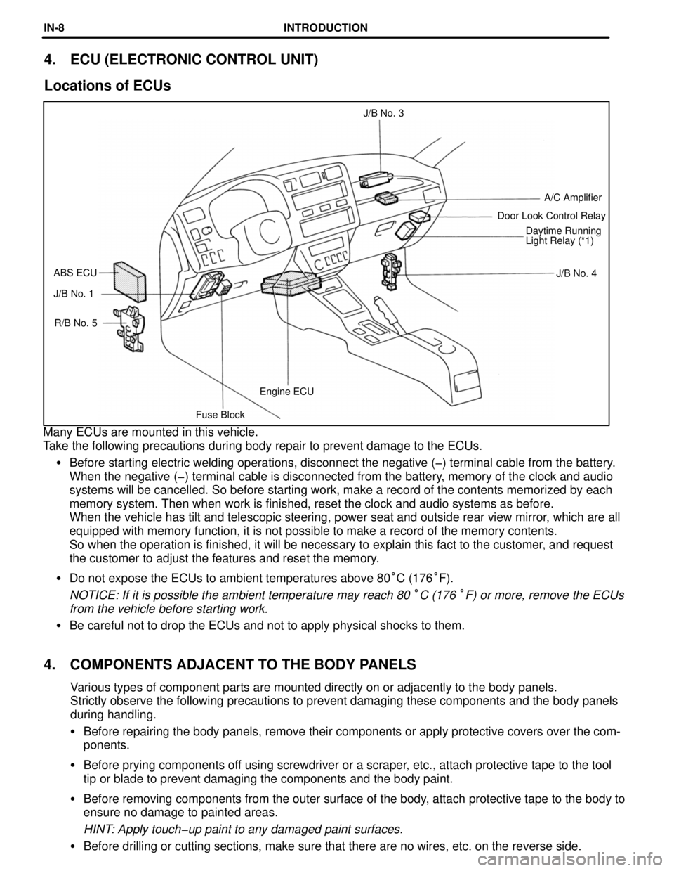
Fuse BlockEngine ECU R/B No. 5 J/B No. 1J/B No. 4 ABS ECUDaytime Running
Light Relay (*1) Door Look Control RelayA/C Amplifier J/B No. 3
4. ECU (ELECTRONIC CONTROL UNIT)
Locations of ECUs
Many ECUs are mounted in this vehicle.
Take the following precautions during body repair to prevent damage to the ECUs.
�Before starting electric welding operations, disconnect the negative (-) terminal cable from the battery.
When the negative (-) terminal cable is disconnected from the battery, memory of the clock and audio
systems will be cancelled. So before starting work, make a record of the contents memorized by each
memory system. Then when work is finished, reset the clock and audio systems as before.
When the vehicle has tilt and telescopic steering, power seat and outside rear view mirror, which are all
equipped with memory function, it is not possible to make a record of the memory contents.
So when the operation is finished, it will be necessary to explain this fact to the customer, and request
the customer to adjust the features and reset the memory.
�Do not expose the ECUs to ambient temperatures above 80°C (176°F).
NOTICE: If it is possible the ambient temperature may reach 80 °C (176 °F) or more, remove the ECUs
from the vehicle before starting work.
�Be careful not to drop the ECUs and not to apply physical shocks to them.
4. COMPONENTS ADJACENT TO THE BODY PANELS
Various types of component parts are mounted directly on or adjacently to the body panels.
Strictly observe the following precautions to prevent damaging these components and the body panels
during handling.
�Before repairing the body panels, remove their components or apply protective covers over the comœ
ponents.
�Before prying components off using screwdriver or a scraper, etc., attach protective tape to the tool
tip or blade to prevent damaging the components and the body paint.
�Before removing components from the outer surface of the body, attach protective tape to the body to
ensure no damage to painted areas.
HINT: Apply touch-up paint to any damaged paint surfaces.
�Before drilling or cutting sections, make sure that there are no wires, etc. on the reverse side.
INTRODUCTIONINœ8
Page 218 of 1354

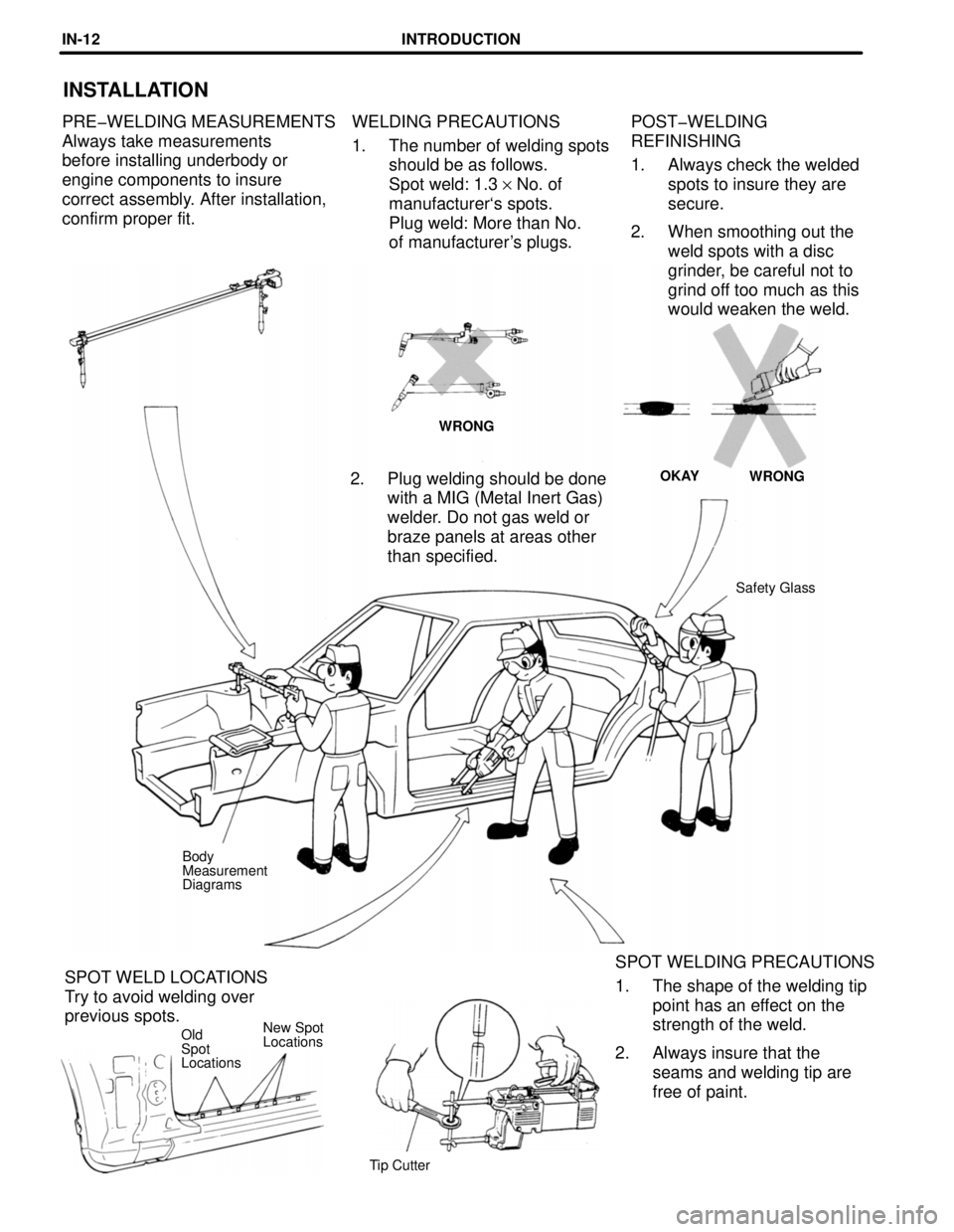
New Spot
Locations
POST-WELDING
REFINISHING
1. Always check the welded
spots to insure they are
secure.
2. When smoothing out the
weld spots with a disc
grinder, be careful not to
grind off too much as this
would weaken the weld.
INSTALLATION
PRE-WELDING MEASUREMENTS
Always take measurements
before installing underbody or
engine components to insure
correct assembly. After installation,
confirm proper fit.WELDING PRECAUTIONS
1. The number of welding spots
should be as follows.
Spot weld: 1.3 y No. of
manufacturer`s spots.
Plug weld: More than No.
of manufacturer's plugs.
WRONG
WRONG OKAY
2. Plug welding should be done
with a MIG (Metal Inert Gas)
welder. Do not gas weld or
braze panels at areas other
than specified.
Safety Glass
Body
Measurement
Diagrams
SPOT WELDING PRECAUTIONS
1. The shape of the welding tip
point has an effect on the
strength of the weld.
2. Always insure that the
seams and welding tip are
free of paint. SPOT WELD LOCATIONS
Try to avoid welding over
previous spots.
Old
Spot
Locations
Tip Cutter
INTRODUCTIONINœ12
Page 223 of 1354
HINT: For symbols, capital letters indicate right side of vehicle,
small letters indicate left side of vehicle (Seen from rear).
K-k
1386
(54.57)552
(21.73)C-K
or
c-k
1494
(58.82)C-k
or
c-K
(Three-Dimensional Distance)
mm (in.)
Hole dia.
6 (0.24) nut
10 (0.39)
10 (0.39)
6 (0.24) nut
10 (0.39) Name
Cooler condenser installation nut
Radiator support extension standard hole
Radiator support standard hole
Front bumper support installation nut
Front apron to cowl side member standard hole Symbol
G, g
H, h
I, i
J
K, k Hole dia.
6 (0.24) nut
11 (0.43)
6 (0.24) nut
13 (0.51)
18 (0.71) Name
Front fender installation nut
Front spring support hole - inner
Front fender installation nut
Cowl top panel center mark
Front side member standard hole
Front side member standard hole Symbol
A, a
B, b
C, c
D, d
E, e
F, f
BODY DIMENSION DRAWINGS
ENGINE COMPARTMENT
BODY DIMENSIONSDIœ3