Page 227 of 1354

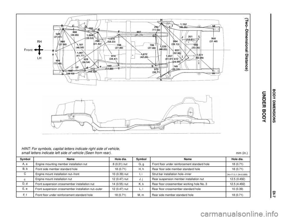
HINT: For symbols, capital letters indicate right side of vehicle,
small letters indicate left side of vehicle (Seen from rear).
(Two-Dimensional Distance)
mm (in.)
Hole dia.
18 (0.71)
18 (0.71)
34y17.5 (1.34y0.689)12.5 (0.492)
12.5 (4.492)
10 (0.39)
18 (0.71) Name
Front floor under reinforcement standard hole
Rear floor side member standard hole
Strut bar installation hole-inner
Rear suspension member installation nut
Rear floor crossmember working hole No. 3
Rear floor crossmember standard hole
Rear side member standard hole Symbol
G, g
H, h
I, i
J, j
K, k
L, l
M, m Hole dia.
8 (0.31) nut
18 (0.71)
10 (0.39) nut
12 (0.47) nut
14 (0.55) nut
12 (0.47) nut
18 (0.71) Name
Engine mounting member installation nut
Front side member standard hole
Engine mount installation nut-front
Engine mount installation nut
Front suspension crossmember installation nut
Front suspension crossmember installation nut-outer
Front floor under reinforcement standard hole Symbol
A, a
B, b
C
c
D, d
E, e
F, f
UNDER BODY
BODY DIMENSIONSDIœ7
Page 228 of 1354

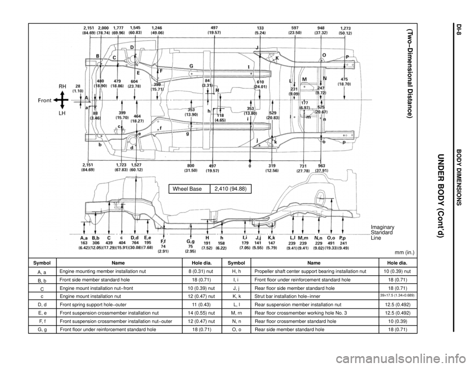
Wheel Base2,410 (94.88)
Imaginary
Standard
Line
mm (in.)
(Two-Dimensional Distance)
Hole dia.
10 (0.39) nut
18 (0.71)
18 (0.71)
39y17.5 (1.34y0.689)12.5 (0.492)
12.5 (0.492)
10 (0.39)
18 (0.71) Name
Propeller shaft center support bearing installation nut
Front floor under reinforcement standard hole
Rear floor side member standard hole
Strut bar installation hole-inner
Rear suspension member installation nut
Rear floor crossmember working hole No. 3
Rear floor crossmember standard hole
Rear side member standard hole Symbol
H, h
I, i
J, j
K, k
L, l
M, rn
N, n
O, o Hole dia.
8 (0.31) nut
18 (0.71)
10 (0.39) nut
12 (0.47) nut
11 (0.43)
14 (0.55) nut
12 (0.47) nut
18 (0.71) Name
Engine mounting member installation nut
Front side member standard hole
Engine mount installation nut-front
Engine mount installation nut
Front spring support hole-outer
Front suspension crossmember installation nut
Front suspension crossmember installation nut-outer
Front floor under reinforcement standard hole Symbol
A, a
B, b
C
c
D, d
E, e
F, f
UNDER BODY (Cont'd)
G, g
BODY DIMENSIONSDIœ8
Page 237 of 1354
mm in.
1.1
4.2
5.3
5.5
6.3
6.4
7.2
7.90.043
0.165
0.209
0.213
0.248
0.252
0.283
0.311
5.5 mm
5.3 mm
FIT STANDARDS
After doors and the engine hood are installed, be sure to perform fit adjustment to prevent abnormal wind
noise and ensure a good appearance.
4.2 mm
7.9
mm
5.5 mm
5.3 mm
6.3 mm
7.2 mm
1.1 mm
6.4 mm
mm (in.): Specified value
APPENDIXAPœ2
Page 275 of 1354
Center Pillar Lower Garnish (PP/PE)
Center Pillar Garnish (PP)
Back Door Trim Board (PP)
Front Pillar Garnish (PP)
Front Fender Liner (PE)
Quater Panel Mudguard (TPU)
Side Turn Signal Light (SAN/ABS)
Washer Jar (PP)
Front Fender Mudguard (TPU)
Radiator Reserve Tank (PP)
Engine Under Cover (PE)
HINT:
wResin material differs with model.
/ Made up of 2 or more kinds of materials.
PLASTIC BODY PARTSPPœ5
Page 278 of 1354

CL04F−03
− CLUTCHTROUBLESHOOTING
CL−1
1996 RAV4 (RM447U)
TROUBLESHOOTING
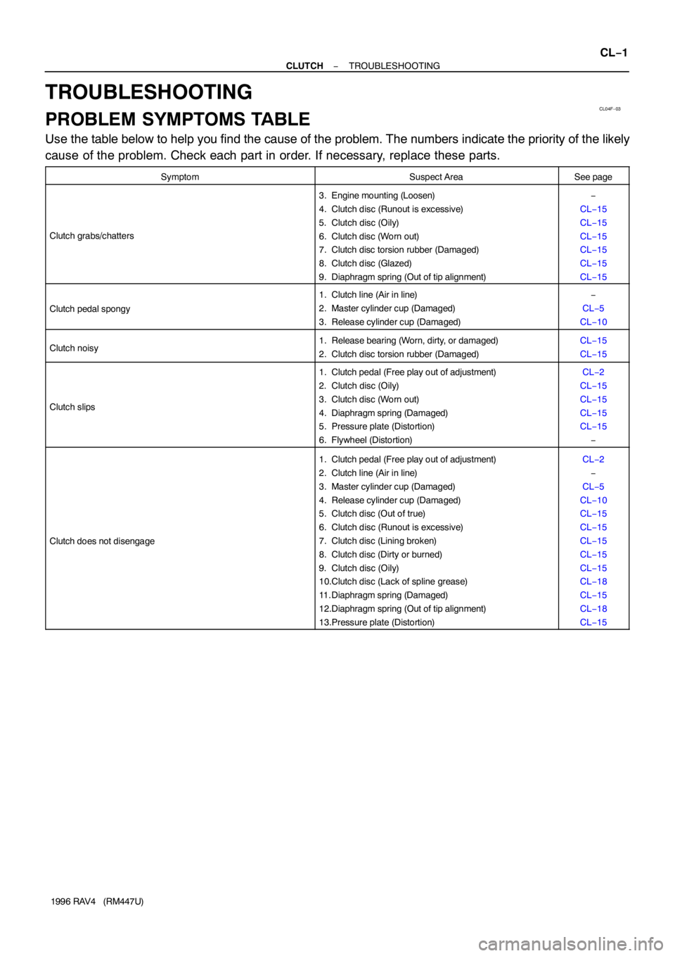
PROBLEM SYMPTOMS TABLE
Use the table below to help you find the cause of the problem. The numbers indicate the priority of the likely
cause of the problem. Check each part in order. If necessary, replace these parts.
SymptomSuspect AreaSee page
Clutch grabs/chatters
3. Engine mounting (Loosen)
4. Clutch disc (Runout is excessive)
5. Clutch disc (Oily)
6. Clutch disc (Worn out)
7. Clutch disc torsion rubber (Damaged)
8. Clutch disc (Glazed)
9. Diaphragm spring (Out of tip alignment)−
CL−15
CL−15
CL−15
CL−15
CL−15
CL−15
Clutch pedal spongy
1. Clutch line (Air in line)
2. Master cylinder cup (Damaged)
3. Release cylinder cup (Damaged)−
CL−5
CL−10
Clutch noisy1. Release bearing (Worn, dirty, or damaged)
2. Clutch disc torsion rubber (Damaged)CL−15
CL−15
Clutch slips
1. Clutch pedal (Free play out of adjustment)
2. Clutch disc (Oily)
3. Clutch disc (Worn out)
4. Diaphragm spring (Damaged)
5. Pressure plate (Distortion)
6. Flywheel (Distortion)CL−2
CL−15
CL−15
CL−15
CL−15
−
Clutch does not disengage
1. Clutch pedal (Free play out of adjustment)
2. Clutch line (Air in line)
3. Master cylinder cup (Damaged)
4. Release cylinder cup (Damaged)
5. Clutch disc (Out of true)
6. Clutch disc (Runout is excessive)
7. Clutch disc (Lining broken)
8. Clutch disc (Dirty or burned)
9. Clutch disc (Oily)
10.Clutch disc (Lack of spline grease)
11. Diaphragm spring (Damaged)
12.Diaphragm spring (Out of tip alignment)
13.Pressure plate (Distortion)CL−2
−
CL−5
CL−10
CL−15
CL−15
CL−15
CL−15
CL−15
CL−18
CL−15
CL−18
CL−15
Page 279 of 1354

Q08873
Push Rod Play
Adjust Point
Pedal Height
Adjust Point
Push Rod
Play
Pedal HeightCL04G−02
CL0042
Pedal Freeplay
CL0512
25 mm (0.98 in.) or more
Release Point
Full Stroke
End Position CL−2
− CLUTCHCLUTCH PEDAL
1996 RAV4 (RM447U)
CLUTCH PEDAL
INSPECTION
1. CHECK PEDAL HEIGHT IS CORRECT
Pedal height from asphalt sheet:
157.6 − 167.6 mm (6.205 − 6.598 in.)
2. IF NECESSARY, ADJUST PEDAL HEIGHT
Loosen the lock nut and turn the stopper bolt until the height is
correct. Tighten the lock nut.
3. CHECK PEDAL FREEPLAY AND PUSH ROD PLAY
(a) Push in on the pedal until the beginning of clutch resis-
tance is felt.
Pedal freeplay: 5.0−15.0 mm (0.197−0.591 in.)
(b) Gently push on the pedal until the resistance begins to in-
crease a little.
Push rod play at pedal top:
1.0−5.0 mm (0.039−0.197 in.)
4. IF NECESSARY, ADJUST PEDAL FREEPLAY AND
PUSH ROD PLAY
(a) Loosen the lock nut and turn the push rod until the free-
play and push rod play are correct.
(b) Tighten the lock nut.
(c) After adjusting the pedal freeplay, check the pedal height.
(d) Connect the air duct and install the lower finish panel.
5. INSPECT CLUTCH RELEASE POINT
(a) Pull the parking brake lever and install wheel stopper.
(b) Start the engine and idle the engine.
(c) Without depressing the clutch pedal, slowly shift the shift
lever into the reverse position until the gears contact.
(d) Gradually depress the clutch pedal and measure the
stroke distance from the point the gear noise stops (re-
lease point) up to the full stroke end position.
Standard distance:
25 mm (0.98 in.) or more
(From pedal stroke end position to release point)
If the distance is not as specified.
�Inspect pedal height.
�Inspect push rod play and pedal freeplay.
�Bleed the clutch line.
�Inspect the clutch cover and disc.
Page 280 of 1354

Q08874
Clutch Start Switch
Q08667
8 ± 0.5 mm
(0.31 ± 0.020 in.)
Q08677
No continuity
321
Q08678
No continuity
321
− CLUTCHCLUTCH PEDAL
CL−3
1996 RAV4 (RM447U)
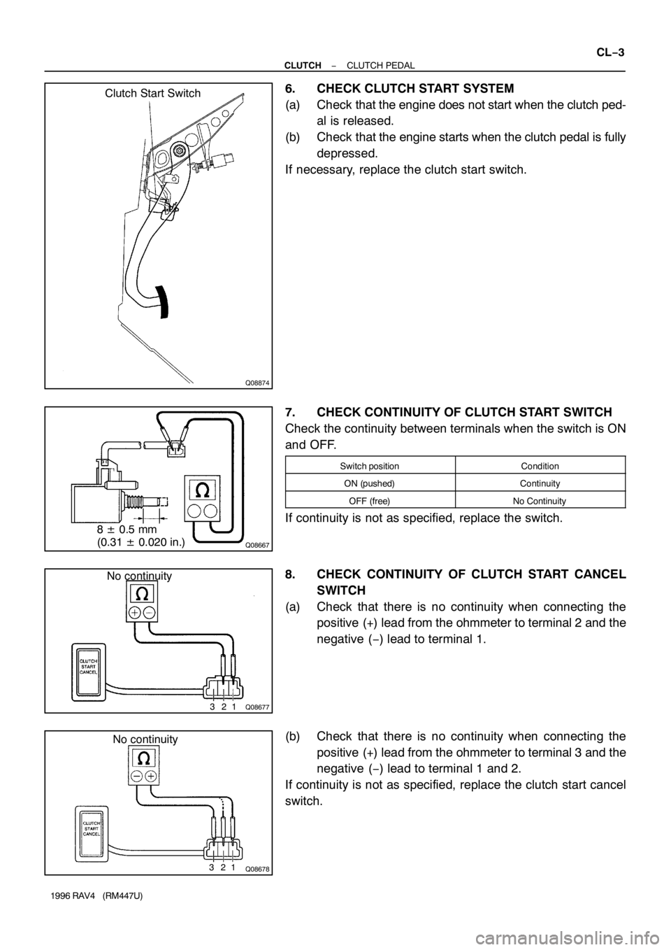
6. CHECK CLUTCH START SYSTEM
(a) Check that the engine does not start when the clutch ped-
al is released.
(b) Check that the engine starts when the clutch pedal is fully
depressed.
If necessary, replace the clutch start switch.
7. CHECK CONTINUITY OF CLUTCH START SWITCH
Check the continuity between terminals when the switch is ON
and OFF.
Switch positionCondition
ON (pushed)Continuity
OFF (free)No Continuity
If continuity is not as specified, replace the switch.
8. CHECK CONTINUITY OF CLUTCH START CANCEL
SWITCH
(a) Check that there is no continuity when connecting the
positive (+) lead from the ohmmeter to terminal 2 and the
negative (−) lead to terminal 1.
(b) Check that there is no continuity when connecting the
positive (+) lead from the ohmmeter to terminal 3 and the
negative (−) lead to terminal 1 and 2.
If continuity is not as specified, replace the clutch start cancel
switch.
Page 293 of 1354
CL04S−02
Q06030
Matchmarks
Q06031
CL−16
− CLUTCHCLUTCH UNIT
1996 RAV4 (RM447U)
REMOVAL
1. REMOVE TRANSAXLE FROM ENGINE
(2WD: See page MX−2)
(4WD: See page MX−8)
2. REMOVE CLUTCH COVER AND DISC
(a) Place matchmarks on the flywheel and clutch cover.
(b) Loosen each set bolt one turn at a time until spring tension
is released.
(c) Remove the set bolts, and pull off the clutch cover with the
clutch disc.
NOTICE:
Do not drop the clutch disc.
3. REMOVE RELEASE BEARING AND FORK FROM
TRANSAXLE
(a) Remove the release bearing together with the fork and
then separate them.
(b) Remove the boot.