Page 933 of 1354

164
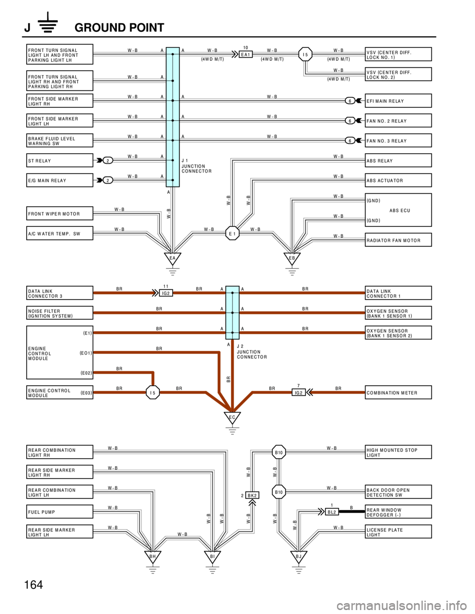
J GROUND POINT
FRONT TURN SIGNAL
LIGHT LH AN D FRO NT
PARKING LIG HT LH
FRONT TURN SIGNAL
LIGHT RH AND FRONT
PARKING LIGHT RH
FRONT SIDE MARKER
LIGHT RH
FRONT SIDE MARKER
LIGHT LH
BRAKE FLUID LEVEL
WARNING SW
ST RELAY
E/G MAIN RELAY
FRON T W IPE R M O TO RVSV (
CENTER DIFF.
LOCK NO. 1)
VSV (
CENTER DIFF.
LOCK NO. 2)
E FI M A IN R E LA Y
FAN NO. 2 RELAY
FAN NO. 3 RELAY
ABS RELAY
ABS ACTUATOR
(
GND)
(
GND)
RADIATOR FAN MOTOR
DATA LINK
CONNECTOR 1
OXYGEN SENSOR
(
BANK 1 SENSOR 1)
OXYGEN SENSOR
(
BANK 1 SENSOR 2)
COMBINATION M ETER
HIGH MOUNTED STOP
LIGHT
BACK DOOR OPEN
DETECTION SW
REAR W INDOW
DEFOGGER (
-)
LICENSE PLATE
LIGHT A/C W ATER TEMP. SW
DATA LINK
CONNECTOR 3
NOISE FILTER
(
IG NITION SY STEM)
ENGINE
CONTROL
MODULE
ENGINE CONTROL
MODULE
REAR COMBINATION
LIGHT RH
REAR SIDE M ARKER
LIGHT RH
REAR COMBINATION
LIGHT LH
FUEL PUM P
REAR SIDE M ARKER
LIGHT LHEA110
I 5
EA EBE 1 A 2
26 6
6
W-B W-B
W-B
W-B
W-B W-B W-B W-B W-B W-B
W-B
W-B
W-B
W-B
W-B W-B
W-B
W-B
W-B
W-B W-B W-B W-B
W-B
W-B W-BABS ECU (
4W D M /T) (
4W D M /T)(
4W D M /T)
(
4W D M /T)
EC IG211
A BR
BR
BRBR
BR
BR
BR
IG 27
I 5 BR BR BR
BR BR BR BR (
E1)
(
EO1)
(
E02)
(
E03)
BH BI BJB10 B10
BL21 BK2 2
W-B W-B W-B W-B
W-B
W-BB W-B W-B
W-B W-B W-B W-B
W-B
W-B W-B
W-B
TIO N
NECTOR
JUNC TIO N
CONNECTOR J 2
A
A
A
A
A
A
AA
A
A
A
JUNC
CON J 1
A
A
AA
A
A
Page 1219 of 1354

S01354
TOYOTA
Hand−Held Tester
SF0Q5−03
S01830
Fuel Inlet Hose
S01827
− SFIFUEL PUMP
SF−5
1996 RAV4 (RM447U)
FUEL PUMP
ON−VEHICLE INSPECTION
1. CHECK FUEL PUMP OPERATION
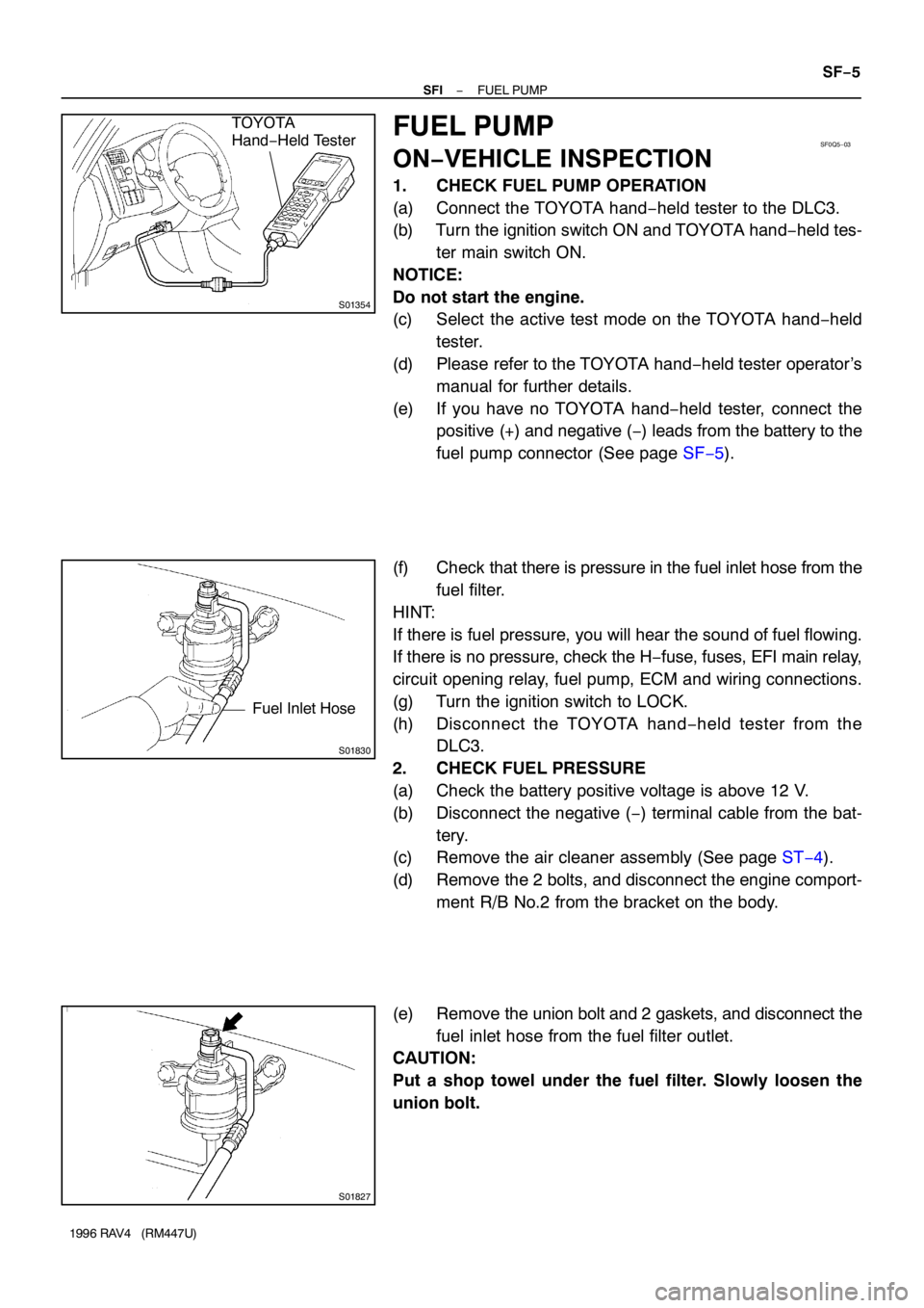
(a) Connect the TOYOTA hand−held tester to the DLC3.
(b) Turn the ignition switch ON and TOYOTA hand−held tes-
ter main switch ON.
NOTICE:
Do not start the engine.
(c) Select the active test mode on the TOYOTA hand−held
tester.
(d) Please refer to the TOYOTA hand−held tester operator’s
manual for further details.
(e) If you have no TOYOTA hand−held tester, connect the
positive (+) and negative (−) leads from the battery to the
fuel pump connector (See page SF−5).
(f) Check that there is pressure in the fuel inlet hose from the
fuel filter.
HINT:
If there is fuel pressure, you will hear the sound of fuel flowing.
If there is no pressure, check the H−fuse, fuses, EFI main relay,
circuit opening relay, fuel pump, ECM and wiring connections.
(g) Turn the ignition switch to LOCK.
(h) Disconnect the TOYOTA hand−held tester from the
DLC3.
2. CHECK FUEL PRESSURE
(a) Check the battery positive voltage is above 12 V.
(b) Disconnect the negative (−) terminal cable from the bat-
tery.
(c) Remove the air cleaner assembly (See page ST−4).
(d) Remove the 2 bolts, and disconnect the engine comport-
ment R/B No.2 from the bracket on the body.
(e) Remove the union bolt and 2 gaskets, and disconnect the
fuel inlet hose from the fuel filter outlet.
CAUTION:
Put a shop towel under the fuel filter. Slowly loosen the
union bolt.
Page 1220 of 1354

S01834
Gasket
SST (Union)
SST
Fuel Inlet Hose Gasket
SST (Union)
S01835
301 − 347 kPa
S01836
For 5 Minutes After Engine has Stopped
147 kPa
or More SF−6
− SFIFUEL PUMP
1996 RAV4 (RM447U)
(f) Install the fuel inlet hose and SST (pressure gauge) to the
fuel filter outlet with the 3 gaskets and SST (union bolt).
SST 09268−45012
Torque: 29 N·m (300 kgf·cm, 22 ft·lbf)
(g) Wipe off any splattered gasoline.
(h) Connect the TOYOTA hand−held tester to the DLC3.
(i) Reconnect the negative (−) terminal cable to the battery.
(j) Turn the ignition switch ON.
(k) Measure the fuel pressure.
Fuel pressure:
301 − 347 kPa (3.1 − 3.5 kgf/cm
2, 44 − 50 psi)
If pressure is high, replace the fuel pressure regulator.
If pressure is low, check these parts:
�Fuel hoses and connections
�Fuel pump
�Fuel filter
�Fuel pressure regulator
(l) Remove the TOYOTA hand−held tester from the DLC3.
(m) Start the engine.
(n) Measure the fuel pressure at idle.
Fuel pressure:
301 − 347 kPa (3.1 − 3.5 kgf/cm
2, 44 − 50 psi)
(o) Stop the engine.
(p) Check that the fuel pressure remains as specified for 5
minutes after the engine has stopped.
Fuel pressure:
147 kPa (1.5 kgf/cm
2, 21 psi) or more
If pressure is not as specified, check the fuel pump, pressure
regulator and/or injectors.
(q) After checking fuel pressure, disconnect the negative (−)
terminal cable from the battery and carefully remove the
SST to prevent gasoline from splashing.
SST 09268−45012
(r) Reconnect the fuel inlet hose with 2 new gaskets and the
union bolt.
Torque: 29 N·m (300 kgf·cm, 21 ft·lbf)
(s) Reconnect the negative (−) terminal cable to the battery.
(t) Check for fuel leakage (See page SF−1).
(u) Reinstall the engine comportment R/B No.2 and air clean-
er assembly.
3. CHECK FUEL PUMP
(a) Remove the LH rear seat assembly.
(b) Remove the floor service hole cover.
Page 1222 of 1354
SF0Q6−01
S01937
3 Door Vehicles
LH Rear Seat Assembly5 Door Vehicles
LH Rear Seat Assembly
37 (375, 27)
37 (375, 27)
Rear Seat Hinge Cover
Floor Service Hole Cover
29 (300, 22)
Fuel Pump & Sender
Gauge Connector
� Gasket
Fuel Suction w/ Pump &
Gauge AssemblyFuel Return
Vent Hose� Gasket
Fuel Outlet Pipe
x 8
� GasketFuel Hose
Fuel Pump Connector
Ground Strap
Fuel Pump
Fuel Pump Filter
Rubber Cushion � Clip Fuel Pump Clamp
N·m (kgf·cm, ft·lbf) : Specified torque
� Non−reusable part SF−8
− SFIFUEL PUMP
1996 RAV4 (RM447U)
COMPONENTS
Page 1223 of 1354

SF0Q7−02
S01828(a)
(b)
S01829
− SFIFUEL PUMP
SF−9
1996 RAV4 (RM447U)
REMOVAL
CAUTION:
Do not smoke or work near an open flame when working on
the fuel pump.
1. REMOVE LH REAR SEAT ASSEMBLY
2. REMOVE FLOOR SERVICE HOLE COVER
(a) Take out the floor carpet.
(b) Remove the 4 screws and service hole cover.
HINT:
At the time of installation, plaese refer to the following items.
Check for fuel leakage (See page SF−1).
3. DISCONNECT FUEL PUMP & SENDER GAUGE CON-
NECTOR
4. DISCONNECT FUEL PIPE AND HOSE FROM FUEL
SUCTION TUBE
CAUTION:
Remove the fuel filler cap to prevent the fuel from flowing
out.
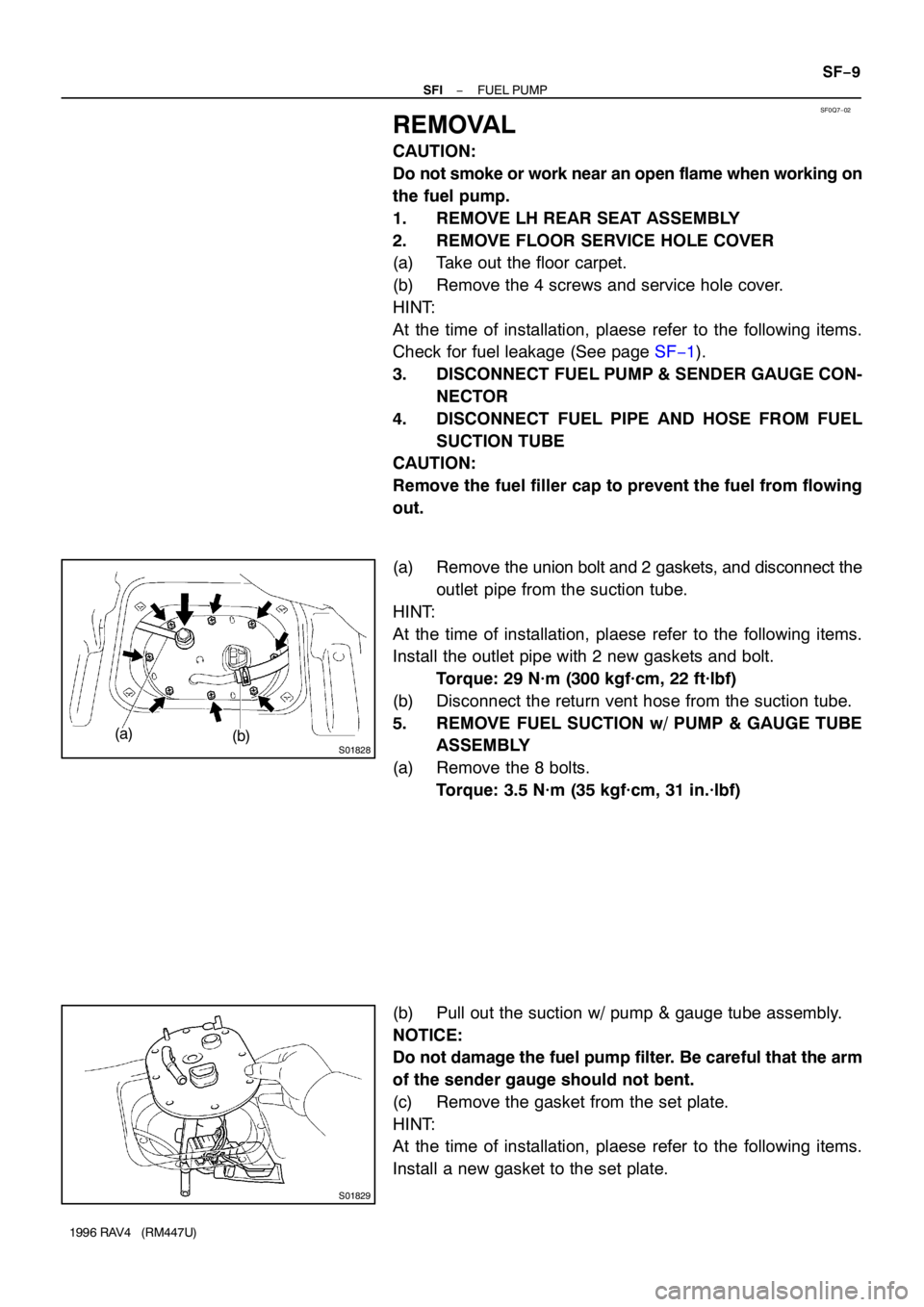
(a) Remove the union bolt and 2 gaskets, and disconnect the
outlet pipe from the suction tube.
HINT:
At the time of installation, plaese refer to the following items.
Install the outlet pipe with 2 new gaskets and bolt.
Torque: 29 N·m (300 kgf·cm, 22 ft·lbf)
(b) Disconnect the return vent hose from the suction tube.
5. REMOVE FUEL SUCTION w/ PUMP & GAUGE TUBE
ASSEMBLY
(a) Remove the 8 bolts.
Torque: 3.5 N·m (35 kgf·cm, 31 in.·lbf)
(b) Pull out the suction w/ pump & gauge tube assembly.
NOTICE:
Do not damage the fuel pump filter. Be careful that the arm
of the sender gauge should not bent.
(c) Remove the gasket from the set plate.
HINT:
At the time of installation, plaese refer to the following items.
Install a new gasket to the set plate.
Page 1224 of 1354
SF0Q8−02
S01896
Pull
FI6376
SF−10
− SFIFUEL PUMP
1996 RAV4 (RM447U)
DISASSEMBLY
1. DISCONNECT FUEL PUMP CONNECTOR
2. REMOVE FUEL PUMP FROM FUEL PUMP BRACKET
(a) Disconnect the ground strap from the fuel pump clamp.
(b) Pull off the lower side of the fuel pump from the pump
bracket.
(c) Disconnect the fuel hose from the fuel pump, and remove
the fuel pump.
(d) Remove the rubber cushion from the fuel pump.
3. REMOVE FUEL PUMP CLAMP
4. REMOVE FUEL PUMP FILTER FROM FUEL PUMP
(a) Using a small screwdriver, remove the clip.
(b) Pull out the pump filter.
HINT:
At the time of installation, plaese refer to the following items.
Install the pump filter with a new clip.
Page 1227 of 1354
SF0QB−01
S01959
3 Door Vehicles
LH Rear Seat Assembly5 Door Vehicles
LH Rear Seat Assembly
37 (375, 27)
37 (375, 27)
Rear Seat Hinge Cover
Floor Service Hole Cover
29 (300, 22)
Fuel Pump & Sender
Gauge Connector
� Gasket
Fuel Suction w/ Pump &
Gauge Tube AssemblyFuel Return
Vent Hose� Gasket
Fuel Outlet Pipe
x 8
� GasketFuel Hose
Fuel Pressure Regulator � O−Ring Fuel Filter
N·m (kgf·cm, ft·lbf) : Specified torque
� Non−reusable partClip
− SFIFUEL PRESSURE REGULATOR
SF−13
1996 RAV4 (RM447U)
FUEL PRESSURE REGULATOR
COMPONENTS
Page 1228 of 1354
SF0QC−02
S01942
S01973
Support Tube
WRONG New O−Ring
Pressure
Regulator
CORRECT
WRONG SF−14
− SFIFUEL PRESSURE REGULATOR
1996 RAV4 (RM447U)
REMOVAL
CAUTION:
Do not smoke or work near an open flame when working on
the fuel pump.
1. REMOVE FUEL SUCTION TUBE (See page SF−9)
2. REMOVE FUEL PRESSURE REGULATOR
(a) Remove the clip from the fuel filter.
(b) Disconnect the fuel hose from the pressure regulator.
(c) Remove the screw, and pull out the pressure regulator.
(d) Remove the O−ring from the pressure regulator.
HINT:
At the time of installation, plaese refer to the following items. Ap-
ply a light coat of gasoline to a new O−ring, and install it to the
pressure regulator.