Page 668 of 1354

EM−2
− ENGINE MECHANICALCO/HC
1996 RAV4 (RM447U)
6. TROUBLESHOOTING
If the CO/HC concentration does not comply with regulations,
troubleshoot in the order given below.
(a) Check the oxygen sensor operation (See page DI−42).
(b) See the table below for possible causes, then inspect and
correct the applicable causes if necessary.
HCCOProblemsCauses
HighNormalRough idle4. Faulty ignitions:
�Incorrect timing
�Fouled, shorted or improperly gapped plugs
�Open or or crossed high−tension cords
�Cracked distributor cap
5. Incorrect valve clearance
6. Leaky EGR valve
7. Leaky intake and exhaust valves
8. Leaky cylinder
HighLowRough idle
(Fluctuating HC reading)1. Vacuum leaks:
�PCV hose
�EGR valve
�Intake manifold
�Throttle body
�IAC valve
�Brake booster line
2. Lean mixture causing misfire
HighHighRough idle
(Black smoke from exhaust)1. Restricted air filter
2. Faulty SFI system:
�Faulty pressure regulator
�Clogged fuel return line
�Defective ECT sensor
�Defective IAT sensor
�Faulty ECM
�Faulty injector
�Faulty throttle position sensor
�MAP sensor
Page 701 of 1354

S01560
(3)(1)
(2)
S01806
S01644
S01791
− ENGINE MECHANICALCYLINDER HEAD
EM−35
1996 RAV4 (RM447U)
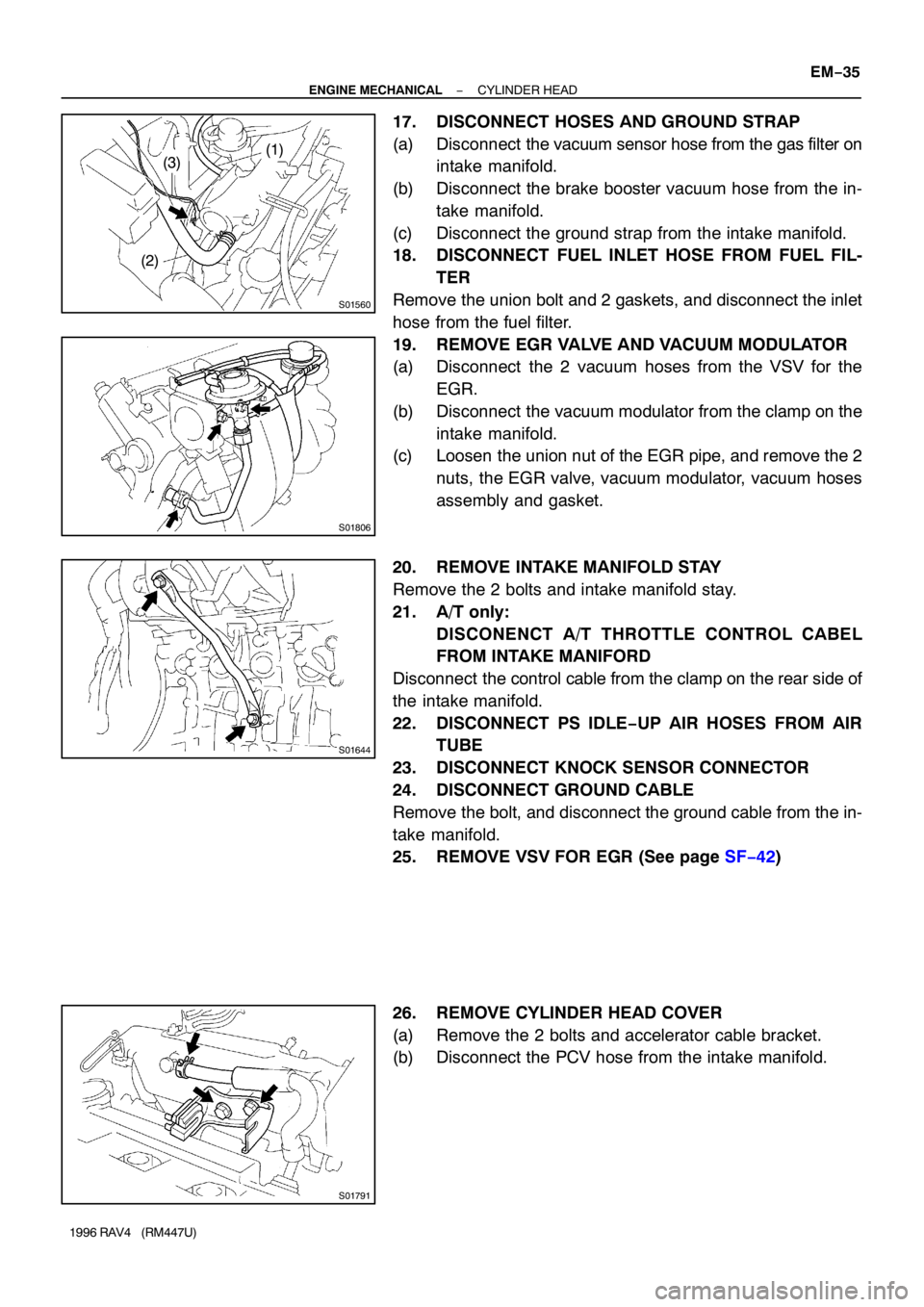
17. DISCONNECT HOSES AND GROUND STRAP
(a) Disconnect the vacuum sensor hose from the gas filter on
intake manifold.
(b) Disconnect the brake booster vacuum hose from the in-
take manifold.
(c) Disconnect the ground strap from the intake manifold.
18. DISCONNECT FUEL INLET HOSE FROM FUEL FIL-
TER
Remove the union bolt and 2 gaskets, and disconnect the inlet
hose from the fuel filter.
19. REMOVE EGR VALVE AND VACUUM MODULATOR
(a) Disconnect the 2 vacuum hoses from the VSV for the
EGR.
(b) Disconnect the vacuum modulator from the clamp on the
intake manifold.
(c) Loosen the union nut of the EGR pipe, and remove the 2
nuts, the EGR valve, vacuum modulator, vacuum hoses
assembly and gasket.
20. REMOVE INTAKE MANIFOLD STAY
Remove the 2 bolts and intake manifold stay.
21. A/T only:
DISCONENCT A/T THROTTLE CONTROL CABEL
FROM INTAKE MANIFORD
Disconnect the control cable from the clamp on the rear side of
the intake manifold.
22. DISCONNECT PS IDLE−UP AIR HOSES FROM AIR
TUBE
23. DISCONNECT KNOCK SENSOR CONNECTOR
24. DISCONNECT GROUND CABLE
Remove the bolt, and disconnect the ground cable from the in-
take manifold.
25. REMOVE VSV FOR EGR (See page SF−42)
26. REMOVE CYLINDER HEAD COVER
(a) Remove the 2 bolts and accelerator cable bracket.
(b) Disconnect the PCV hose from the intake manifold.
Page 727 of 1354

S01791
S01644
S01806
− ENGINE MECHANICALCYLINDER HEAD
EM−61
1996 RAV4 (RM447U)
(i) Connect the PCV hose to the intake manifold.
(j) Install the accelerator cable bracket with the 2 bolts.
17. INSTALL VSV FOR EGR (See page SF−42)
18. CONNECT GROUND CABLE
Connect the ground cable to the intake manifold with the bolt.
19. CONNECT KNOCK SENSOR CONNECTOR
20. CONNECT PS IDLE−UP AIR HOSES TO AIR TUBE
21. A/T only:
CONNECT A/T THROTTLE CONTROL CABLE TO IN-
TAKE MANIFOLD
Connect the control cable to the clamp on the rear side of the
intake manifold.
22. INSTALL INTAKE MANIFOLD STAY
Install the intake manifold stay with the 2 bolts.
Torque: 42 N·m (425 kgf·cm, 31 ft·lbf)
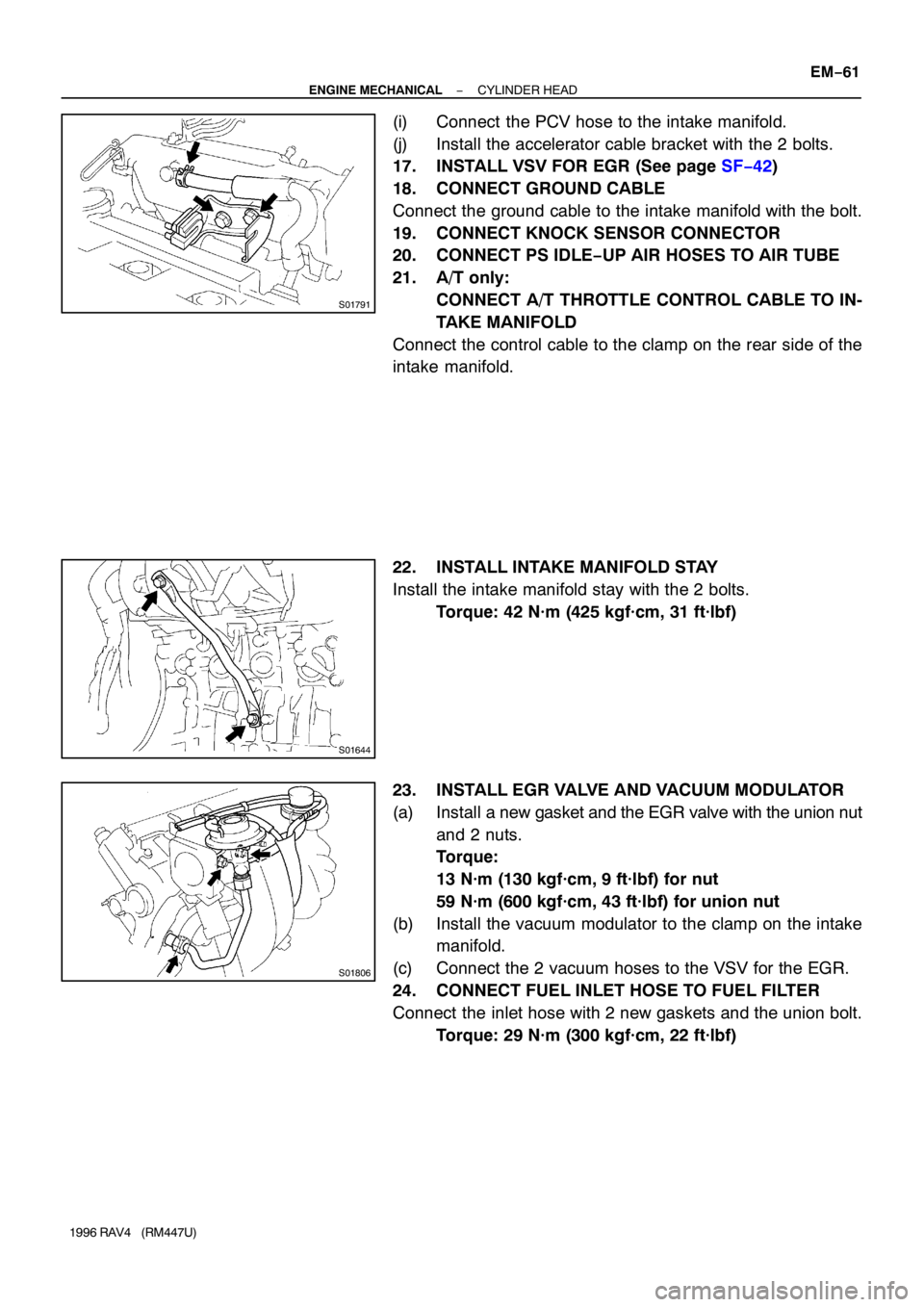
23. INSTALL EGR VALVE AND VACUUM MODULATOR
(a) Install a new gasket and the EGR valve with the union nut
and 2 nuts.
Torque:
13 N·m (130 kgf·cm, 9 ft·lbf) for nut
59 N·m (600 kgf·cm, 43 ft·lbf) for union nut
(b) Install the vacuum modulator to the clamp on the intake
manifold.
(c) Connect the 2 vacuum hoses to the VSV for the EGR.
24. CONNECT FUEL INLET HOSE TO FUEL FILTER
Connect the inlet hose with 2 new gaskets and the union bolt.
Torque: 29 N·m (300 kgf·cm, 22 ft·lbf)
Page 731 of 1354
EM0EV−02
A04063
N·m (kgf·cm, ft·lbf) : Specified torque
� Non−reusable part
29 (300, 22)
Hold Down ClampHold Down Clamp
BatteryEngine Hood
Battery Tray
Lower Radiator
HosePS Pump
w/ BracketCharcoal Canister
Battery Tray
IAT Sensor ConnectorAir Cleaner Cap
� Gasket
� Gasket
Fuel Inlet Hose
Fuel Filter
Water Inlet
Upper Radiator
Hose
Heater Hose
PS Pump Drive Belt
Generator Drive
Belt
Accelerator Cable
Generator
Generator Drive Belt
Adjusting Bar
Air Filter
EVAP VSV Connector
Air Cleaner Case
Radiator
Reservoir
Relay Block No. 2
Upper Cover
Relay Block No. 2
Wire Harness
A/C Compressor
Type B Type A
Type B Type A
− ENGINE MECHANICALENGINE UNIT
EM−65
1996 RAV4 (RM447U)
ENGINE UNIT
COMPONENTS
Page 799 of 1354
29
G
Position of Parts in Engine Compartment
I 1 Idle Air Control Valve R 1Radiator Fan Motor
I 2 Igniter R 2 Rear Washer Motor
I 3 Ignition Coil and Distributor
I 4 Ignition Coil and Distributor S 1 Solenoid Valve SLD
I 5 Injector No. 1 S 2 Starter
I 6 Injector No. 2 S 3 Starter
I 7 Injector No. 3
I 8 Injector No. 4 T 1 Throttle Position Sensor
I 9 Intake Air Temp. Sensor
V 1 Vapor Pressure Sensor
K 1 Knock Sensor V 2 Vehicle Speed Sensor (Combination Meter)
V 3 Vehicle Speed Sensor (Front)
M 1 Manifold Absolute Pressure Sensor V 4 Vehicle Speed Sensor (Rear)
V 5 VSV (Center Diff. Lock No. 1)
N 1 Noise Filter (Ignition System) V 6 VSV (Center Diff. Lock No. 2)
V 7 VSV (EGR)
O 1 Oil Pressure SW V 8 VSV (EVAP)
O 2 Oxygen Sensor (Bank 1 Sensor 1) V 9 VSV (Vapor Pressure Sensor)
O 3 Oxygen Sensor (Bank 1 Sensor 2)
W 1 Water Temp. Sender
P 1 Park/Neutral Position SW (A/T)
Page 836 of 1354
67
IG 1 12 I 5 B-O
B-W(
A/T)
R-W
G-R
B-Y
B-RB-R B-R B-O
B-R B-R B-R B-R B-R B-RB-R
B
B-O
B
G-
B-
B-
R-Y
Y-GN 1
FROM A/C AMPLIFIER
TO A/C AMPLIFIERB-
B-
B-Y
B-RIG 1 10
EA1 9
EC B (
M/T)I 4
I 4I 4I 5I 5
I 5 B
BR
B
B BR
B
R
(
M/T)(
A/T) (
A/T)
(
A/T)
(
A/T)
(
A/T)
JU N TO R J 2
TO ST RELAY
B-R
B-R
B-R
B-R E
A AA B-W
B
-WB-W(
M/T)
(
A/T)
(
A/T) JUNCTION CONNECTOR J 5
C 1
BATTC 22
NEWA 10
IS C OA 9
ISC CA 23
EGRB 8
TPCA 22
EVP
C 11STA
C 14FC
A 11#20
A 12#10
C 21ACT
C 10AC1 2 1P
N
B BR
R
Y
RB-L
B-Y
B-W
R-W
P R-W
B-WPARK/NEUTRAL
POSITION SW NOISE FILTER
(
IGNITION SYSTEM)ENGINE CONTROL MODULEB E 4 , E 5AC, E 6
A 24 A25
Y
R
IB2 20
A 3
B 6 B 5A 2(
2W D)
(
4W D)
(
2WD)
(
4WD)
I 5
B-W
B-W B-W
B-W (
M/T) (
M/T)
(
A/T)
(
A/T) C C 8
B P 1 , A#40 #30
(
A/T)
AC C A
B B-W
B-W(
A/T)
(
A/T)(
M/T) CTION CONNECJUN CTIO N
CONNECTOR J 513
ID
C
V
NSI 1 2
2 1
1 2 2LE AIR
ONTROL VALVE
VSV (
EGR)
(
VAPOR PRESSUR
OR)
VSV (
EVAP) 1
V 7
V 8 VS
SE V 9
2 1LUTCH START SW
Page 1219 of 1354

S01354
TOYOTA
Hand−Held Tester
SF0Q5−03
S01830
Fuel Inlet Hose
S01827
− SFIFUEL PUMP
SF−5
1996 RAV4 (RM447U)
FUEL PUMP
ON−VEHICLE INSPECTION
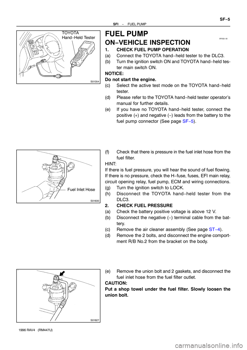
1. CHECK FUEL PUMP OPERATION
(a) Connect the TOYOTA hand−held tester to the DLC3.
(b) Turn the ignition switch ON and TOYOTA hand−held tes-
ter main switch ON.
NOTICE:
Do not start the engine.
(c) Select the active test mode on the TOYOTA hand−held
tester.
(d) Please refer to the TOYOTA hand−held tester operator’s
manual for further details.
(e) If you have no TOYOTA hand−held tester, connect the
positive (+) and negative (−) leads from the battery to the
fuel pump connector (See page SF−5).
(f) Check that there is pressure in the fuel inlet hose from the
fuel filter.
HINT:
If there is fuel pressure, you will hear the sound of fuel flowing.
If there is no pressure, check the H−fuse, fuses, EFI main relay,
circuit opening relay, fuel pump, ECM and wiring connections.
(g) Turn the ignition switch to LOCK.
(h) Disconnect the TOYOTA hand−held tester from the
DLC3.
2. CHECK FUEL PRESSURE
(a) Check the battery positive voltage is above 12 V.
(b) Disconnect the negative (−) terminal cable from the bat-
tery.
(c) Remove the air cleaner assembly (See page ST−4).
(d) Remove the 2 bolts, and disconnect the engine comport-
ment R/B No.2 from the bracket on the body.
(e) Remove the union bolt and 2 gaskets, and disconnect the
fuel inlet hose from the fuel filter outlet.
CAUTION:
Put a shop towel under the fuel filter. Slowly loosen the
union bolt.
Page 1220 of 1354

S01834
Gasket
SST (Union)
SST
Fuel Inlet Hose Gasket
SST (Union)
S01835
301 − 347 kPa
S01836
For 5 Minutes After Engine has Stopped
147 kPa
or More SF−6
− SFIFUEL PUMP
1996 RAV4 (RM447U)
(f) Install the fuel inlet hose and SST (pressure gauge) to the
fuel filter outlet with the 3 gaskets and SST (union bolt).
SST 09268−45012
Torque: 29 N·m (300 kgf·cm, 22 ft·lbf)
(g) Wipe off any splattered gasoline.
(h) Connect the TOYOTA hand−held tester to the DLC3.
(i) Reconnect the negative (−) terminal cable to the battery.
(j) Turn the ignition switch ON.
(k) Measure the fuel pressure.
Fuel pressure:
301 − 347 kPa (3.1 − 3.5 kgf/cm
2, 44 − 50 psi)
If pressure is high, replace the fuel pressure regulator.
If pressure is low, check these parts:
�Fuel hoses and connections
�Fuel pump
�Fuel filter
�Fuel pressure regulator
(l) Remove the TOYOTA hand−held tester from the DLC3.
(m) Start the engine.
(n) Measure the fuel pressure at idle.
Fuel pressure:
301 − 347 kPa (3.1 − 3.5 kgf/cm
2, 44 − 50 psi)
(o) Stop the engine.
(p) Check that the fuel pressure remains as specified for 5
minutes after the engine has stopped.
Fuel pressure:
147 kPa (1.5 kgf/cm
2, 21 psi) or more
If pressure is not as specified, check the fuel pump, pressure
regulator and/or injectors.
(q) After checking fuel pressure, disconnect the negative (−)
terminal cable from the battery and carefully remove the
SST to prevent gasoline from splashing.
SST 09268−45012
(r) Reconnect the fuel inlet hose with 2 new gaskets and the
union bolt.
Torque: 29 N·m (300 kgf·cm, 21 ft·lbf)
(s) Reconnect the negative (−) terminal cable to the battery.
(t) Check for fuel leakage (See page SF−1).
(u) Reinstall the engine comportment R/B No.2 and air clean-
er assembly.
3. CHECK FUEL PUMP
(a) Remove the LH rear seat assembly.
(b) Remove the floor service hole cover.