Page 767 of 1354

P13450
P13448
Z17147
Front Mark
(Cavity)
FrontPush
P13451
Front Mark
(Protrusion)
P13441
− ENGINE MECHANICALCYLINDER BLOCK
EM−101
1996 RAV4 (RM447U)
(b) Install the 5 main bearing caps in their proper locations.
HINT:
Each bearing cap has a number and front mark.
(c) Apply a light coat of engine oil on the threads and under
the heads of the main bearing cap bolts.
(d) Install and uniformly tighten the 10 bolts of the main bear-
ing caps, in several passes, in the sequence shown.
Torque: 59 N·m (600 kgf·cm, 43 ft·lbf)
(e) Check that the crankshaft turns smoothly.
(f) Check the crankshaft thrust clearance (See page
EM−81).
8. INSTALL PISTON AND CONNECTING ROD AS-
SEMBLES
(a) Cover the connecting rod bolts with a short piece of hose
to protect the crankshaft from damage.
(b) Using a piston ring compressor, push the correctly num-
bered piston and connecting rod assemblies into each
cylinder with the front mark of the piston facing forward.
9. INSTALL CONNECTING ROD CAPS
(a) Place the connecting rod cap on the connecting rod.
(1) Match the numbered connecting rod cap with the
connecting rod.
(2) Install the connecting rod cap with the front mark
facing forward.
(b) Install the connecting rod cap nuts.
HINT:
�The cap nuts are tightened in 2 progressive steps (steps
(b) and (d)).
�If any one of the connecting rod bolts is broken or de-
formed, replace it.
(1) Apply a light coat of engine oil on the threads and
under the nuts of the connecting rod cap.
(2) Install and alternately tighten the 2 cap nuts in sev-
eral passes.
Page 768 of 1354
P13453
Painted Mark
90°90°
P05527
S01632
SST
P15371
New O−Ring EM−102
− ENGINE MECHANICALCYLINDER BLOCK
1996 RAV4 (RM447U)
Torque: 25 N·m (250 kgf·cm, 18 ft·lbf)
If any one of the cap nuts does not meet the torque specifica-
tion, replace the connecting rod bolt and cap nut as a set.
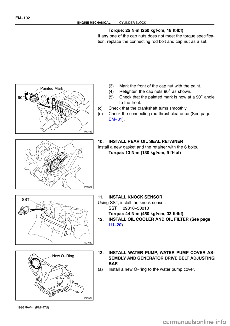
(3) Mark the front of the cap nut with the paint.
(4) Retighten the cap nuts 90° as shown.
(5) Check that the painted mark is now at a 90° angle
to the front.
(c) Check that the crankshaft turns smoothly.
(d) Check the connecting rod thrust clearance (See page
EM−81).
10. INSTALL REAR OIL SEAL RETAINER
Install a new gasket and the retainer with the 6 bolts.
Torque: 13 N·m (130 kgf·cm, 9 ft·lbf)
11. INSTALL KNOCK SENSOR
Using SST, install the knock sensor.
SST 09816−30010
Torque: 44 N·m (450 kgf·cm, 33 ft·lbf)
12. INSTALL OIL COOLER AND OIL FILTER (See page
LU−20)
13. INSTALL WATER PUMP, WATER PUMP COVER AS-
SEMBLY AND GENERATOR DRIVE BELT ADJUSTING
BAR
(a) Install a new O−ring to the water pump cover.
Page 769 of 1354
Z17349
3
1
2
P15304
RH Engine
Mounting
Bracket
PS Pump
Bracket
P13432
EM7333
P15298
3
1
2 M/T
5
8 7
6
4
− ENGINE MECHANICALCYLINDER BLOCK
EM−103
1996 RAV4 (RM447U)
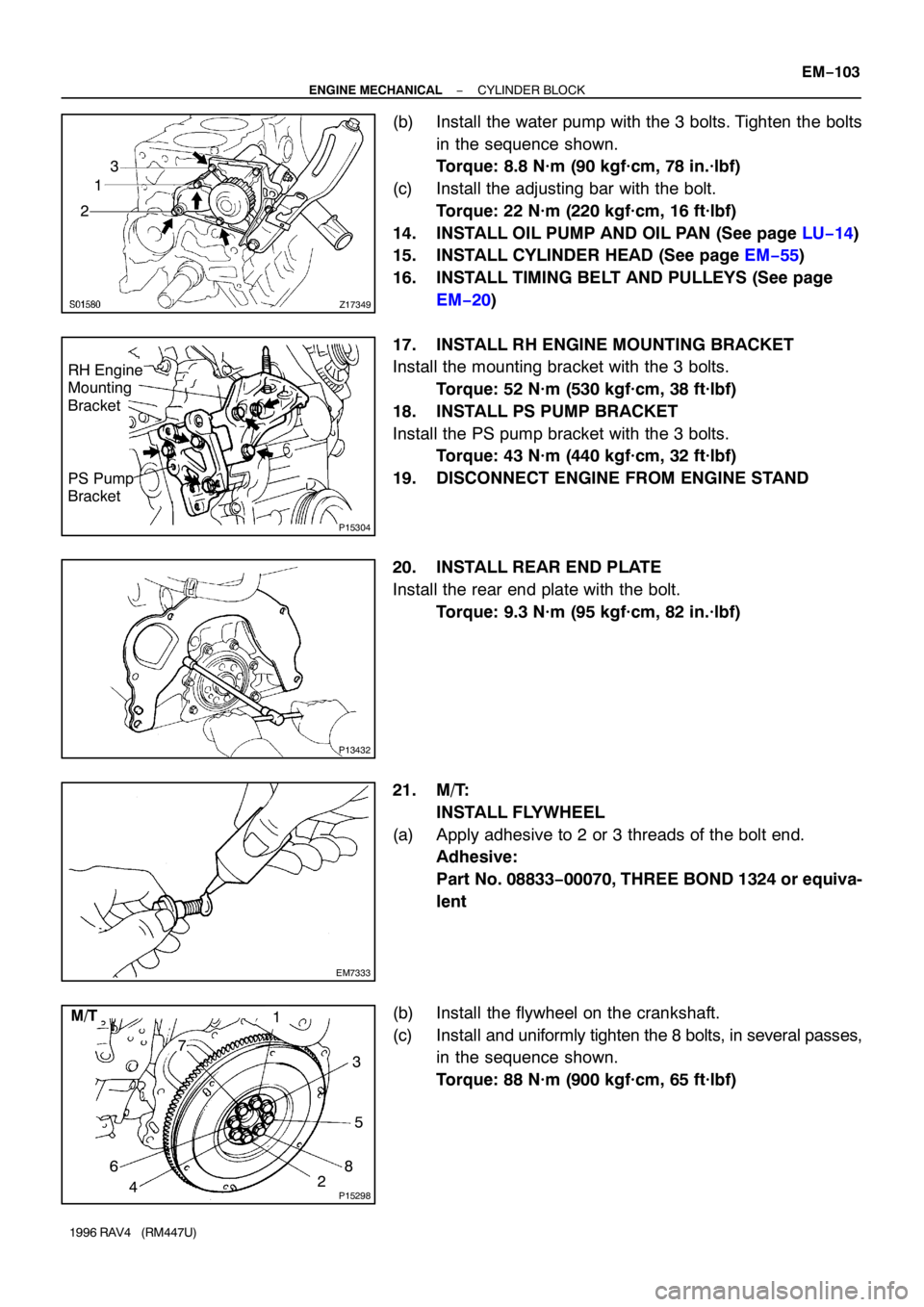
(b) Install the water pump with the 3 bolts. Tighten the bolts
in the sequence shown.
Torque: 8.8 N·m (90 kgf·cm, 78 in.·lbf)
(c) Install the adjusting bar with the bolt.
Torque: 22 N·m (220 kgf·cm, 16 ft·lbf)
14. INSTALL OIL PUMP AND OIL PAN (See page LU−14)
15. INSTALL CYLINDER HEAD (See page EM−55)
16. INSTALL TIMING BELT AND PULLEYS (See page
EM−20)
17. INSTALL RH ENGINE MOUNTING BRACKET
Install the mounting bracket with the 3 bolts.
Torque: 52 N·m (530 kgf·cm, 38 ft·lbf)
18. INSTALL PS PUMP BRACKET
Install the PS pump bracket with the 3 bolts.
Torque: 43 N·m (440 kgf·cm, 32 ft·lbf)
19. DISCONNECT ENGINE FROM ENGINE STAND
20. INSTALL REAR END PLATE
Install the rear end plate with the bolt.
Torque: 9.3 N·m (95 kgf·cm, 82 in.·lbf)
21. M/T:
INSTALL FLYWHEEL
(a) Apply adhesive to 2 or 3 threads of the bolt end.
Adhesive:
Part No. 08833−00070, THREE BOND 1324 or equiva-
lent
(b) Install the flywheel on the crankshaft.
(c) Install and uniformly tighten the 8 bolts, in several passes,
in the sequence shown.
Torque: 88 N·m (900 kgf·cm, 65 ft·lbf)
Page 786 of 1354
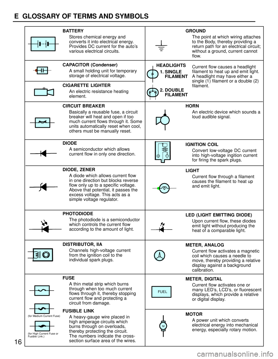
METER, ANALOG
Current flow activates a magnetic
coil which causes a needle to
move, thereby providing a relative
display against a background
calibration. LED (LIGHT EMITTING DIODE)
Upon current flow, these diodes
emit light without producing the
heat of a comparable light. IGNITION COIL
Convert low-voltage DC current
into high-voltage ingition current
for firing the spark plugs. 1. SINGLE
FILAMENT
GROUND
The point at which wiring attaches
to the Body, thereby providing a
return path for an electrical circuit;
without a ground, current cannot
flow.
Current flow causes a headlight
filament to heat up and emit light.
A headlight may have either a
single (1) filament or a double (2)
filament. BATTERY
Stores chemical energy and
converts it into electrical energy.
Provides DC current for the auto's
various electrical circuits.
CAPACITOR (Condenser)
A small holding unit for temporary
storage of electrical voltage.
CIRCUIT BREAKER
Basically a reusable fuse, a circuit
breaker will heat and open if too
much current flows through it. Some
units automatically reset when cool,
others must be manually reset.
DIODE
A semiconductor which allows
current flow in only one direction.
DIODE, ZENER
A diode which allows current flow
in one direction but blocks reverse
flow only up to a specific voltage.
Above that potential, it passes the
excess voltage. This acts as a
simple voltage regulator.
PHOTODIODE
The photodiode is a semiconductor
which controls the current flow
according to the amount of light.
FUSE
A thin metal strip which burns
through when too much current
flows through it, thereby stopping
current flow and protecting a
circuit from damage.
FUSIBLE LINK
A heavy-gauge wire placed in
high amperage circuits which
burns through on overloads,
thereby protecting the circuit.
The numbers indicate the cross-
section surface area of the wires.HORN
An electric device which sounds a
loud audible signal.
LIGHT
Current flow through a filament
causes the filament to heat up
and emit light.
METER, DIGITAL
Current flow activates one or
many LED's, LCD's, or fluorescent
displays, which provide a relative
or digital display.
MOTOR
A power unit which converts
electrical energy into mechanical
energy, especially rotary motion. CIGARETTE LIGHTER
An electric resistance heating
element.
DISTRIBUTOR, IIA
Channels high-voltage current
from the ignition coil to the
individual spark plugs.2. DOUBLE
FILAMENT HEADLIGHTS
FUEL
(for High Current Fuse or
Fusible Link.)
(for Medium Current Fuse)
M
16
E GLOSSARY OF TERMS AND SYMBOLS
Page 787 of 1354
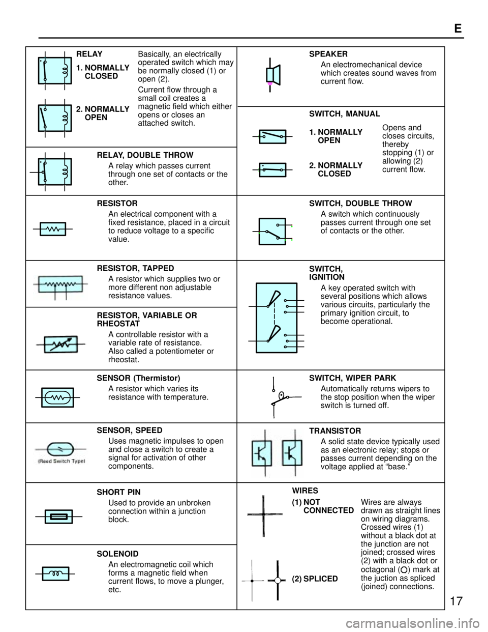
17
E
1. NORMALLY
OPENOpens and
closes circuits,
thereby
stopping (1) or
allowing (2)
current flow.
RESISTOR
An electrical component with a
fixed resistance, placed in a circuit
to reduce voltage to a specific
value.
RESISTOR, TAPPED
A resistor which supplies two or
more different non adjustable
resistance values.
SENSOR (Thermistor)
A resistor which varies its
resistance with temperature.
SHORT PIN
Used to provide an unbroken
connection within a junction
block.
SOLENOID
An electromagnetic coil which
forms a magnetic field when
current flows, to move a plunger,
etc.SWITCH, DOUBLE THROW
A switch which continuously
passes current through one set
of contacts or the other.
SWITCH,
IGNITION
A key operated switch with
several positions which allows
various circuits, particularly the
primary ignition circuit, to
become operational.
Wires are always
drawn as straight lines
on wiring diagrams.
Crossed wires (1)
without a black dot at
the junction are not
joined; crossed wires
(2) with a black dot or
octagonal (
) mark at
the juction as spliced
(joined) connections. RELAY, DOUBLE THROW
A relay which passes current
through one set of contacts or the
other.
SENSOR, SPEED
Uses magnetic impulses to open
and close a switch to create a
signal for activation of other
components.TRANSISTOR
A solid state device typically used
as an electronic relay; stops or
passes current depending on the
voltage applied at base.º SWITCH, WIPER PARK
Automatically returns wipers to
the stop position when the wiper
switch is turned off. SWITCH, MANUAL SPEAKER
An electromechanical device
which creates sound waves from
current flow.
2. NORMALLY
CLOSED
RESISTOR, VARIABLE OR
RHEOSTAT
A controllable resistor with a
variable rate of resistance.
Also called a potentiometer or
rheostat. 2. NORMALLY
OPEN RELAY
1. NORMALLY
CLOSEDBasically, an electrically
operated switch which may
be normally closed (1) or
open (2).
Current flow through a
small coil creates a
magnetic field which either
opens or closes an
attached switch.
(2) SPLICED WIRES
(1) NOT
CONNECTED
Page 799 of 1354
29
G
Position of Parts in Engine Compartment
I 1 Idle Air Control Valve R 1Radiator Fan Motor
I 2 Igniter R 2 Rear Washer Motor
I 3 Ignition Coil and Distributor
I 4 Ignition Coil and Distributor S 1 Solenoid Valve SLD
I 5 Injector No. 1 S 2 Starter
I 6 Injector No. 2 S 3 Starter
I 7 Injector No. 3
I 8 Injector No. 4 T 1 Throttle Position Sensor
I 9 Intake Air Temp. Sensor
V 1 Vapor Pressure Sensor
K 1 Knock Sensor V 2 Vehicle Speed Sensor (Combination Meter)
V 3 Vehicle Speed Sensor (Front)
M 1 Manifold Absolute Pressure Sensor V 4 Vehicle Speed Sensor (Rear)
V 5 VSV (Center Diff. Lock No. 1)
N 1 Noise Filter (Ignition System) V 6 VSV (Center Diff. Lock No. 2)
V 7 VSV (EGR)
O 1 Oil Pressure SW V 8 VSV (EVAP)
O 2 Oxygen Sensor (Bank 1 Sensor 1) V 9 VSV (Vapor Pressure Sensor)
O 3 Oxygen Sensor (Bank 1 Sensor 2)
W 1 Water Temp. Sender
P 1 Park/Neutral Position SW (A/T)
Page 829 of 1354
60
IGNITION
IG 1 11
IG 1 4
20A
AM2
2 2
A
ECJ 2
JUNC
CON21 4 EA1 7
B-R B-R B-R
B-Y B- O
B-W W
B
L- YG
B- W B-O B
B-O
DISTRIBUTOR
BATTERYIGNITION
COIL
BR
B
A 2A1 G- G+ B1
B2 IGNITION COIL AND DISTRIBUTORB I 3 , I 4
A
20 21
2
E
OCK
A
B-O
I 5
W
I 4
(
SHIELDED)
(
SHIELDED)
AIG 2 8
4
NCTION
ONNECTOR
B TO TA C H
[C O M B .
TO A/C AM PRIFIER
1 2
CRANKSH
POSITION
SENSOR C 2
R
1D 8
1H 14
CB
IG T IGF EXT 53
IG N ITER I 2
AFT
TIO N
NECTORNE- IGT IGF
E 4
ENGINE CONTROL
MODULEG+ NE+
R
417 5 20 3J
BB
OM ETER
METER]G
IG NITION S W I1 0 AM1ACC
IG 1
76AM2 IG2
ST2
80A M AIN
FUSIBL
LINK BL F 7
U
DJ
C
DD
Page 837 of 1354
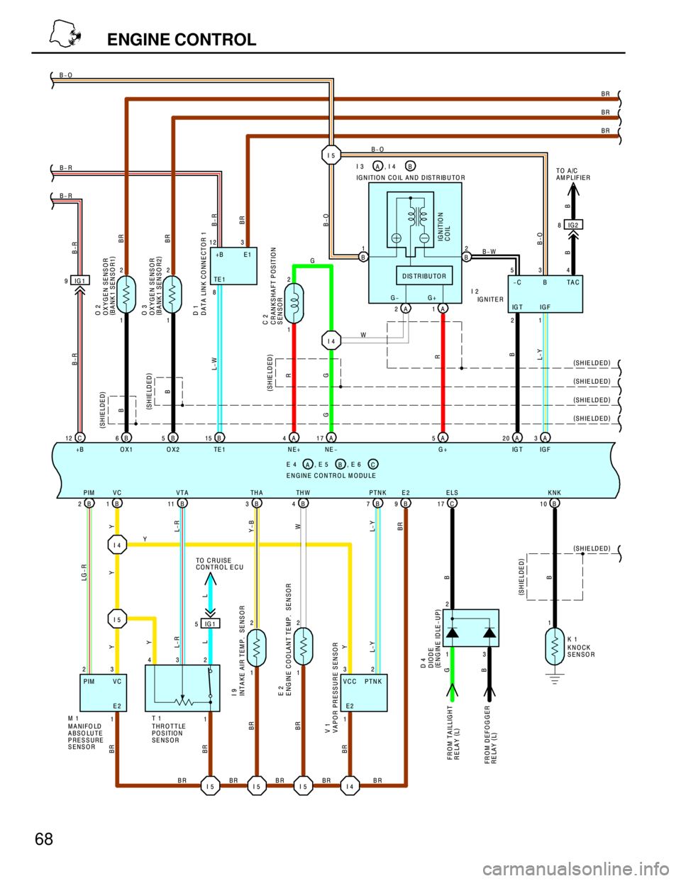
68
ENGINE CONTROL
I 4 IG 1 9
C 12
+BB 6
OX1B 5
OX2B 15
TE 1
B 2PIM
B 1VC
B 11VTA
B 3TH A
B 4TH W
B 7PTNK
B 9E2 B- R B- R B-O
BR
BR
Y
BR BR BR
B-R B-R
L-W B- R
BR LG-R
YY
L-R
Y-B
W
L- Y
BR BR
BR
B
B
BR
BR(
SHIELDED) (
SHIELDED)
A 5
G+ A 4
NE+A 17
NE -A 3
IG F
C 17ELS
B 10KNK
2
B B
(
SHIELDED)
(
SHIELDED)
MANIFOLD
ABSO LUTE
PRESSURE
SENSORTHROTTLE
POSITION
SENSOR
FROM TAI
RELAY (
L)
FR O M D EF
RELAY (
L)
CK
SO R ENGINE CONTROL MODULEB E 4 , E 5
AC, E 6
ENSOR
A 2 G-
A 1 G+ IGNITION COIL AND DISTRIBUTOR
I I 2 B1
B2
DISTRIBUTOR
B-O
BB-O
IG N ITIO N
COIL
A 20
IG T
R
G
R
B
L-Y (
SHIELDED)
BRB-O
1 2
1 2
OXYGEN SENSOR
(
BANK 1 SENSO R1)
OXYGEN SENSOR
(
BANK 1 SENSO R2) O 2
O 3
L
TO CRUISE
CONTROL ECU
V V
BR
B BBR
BR (
SHIELDED) (
SHIELDED)
I 5 I 5 I 5 I 4
DATA LINK CO NNECTOR 1 D 1
(
SHIELDED) (
SHIELDED)
B
TO A/C
AM PLIFIER
B-W
I 4W
G
I 5
B I 3 , I 4
A
IG2 8
1 2
CRANKSHAFT POSITION
SENSOR C 2
G
1 2
1 2
1 3 232
E2
Y
R
R
Y
L-Y
VCC PTNK1
G
BL-R
L Y
INTAKE AIR TEM P. SENSOR I 9
DIO
(
EN D 4
LLIG H T
OGGER
KNO
SEN K 1
ENGINE COOLANT TEMP. S E 2
IG 1 5
APOR PRESSURE SENSOR 1
I 5
8 12 3
TE 1+B E1
534
-C B TAC
IG T IG F
21 GNITER
3 1DE
GINE IDLE-UP)
1E2 VC PIM
M 11 432
T 1