Page 759 of 1354
S01246
Z00064
Z00065
EM7538
− ENGINE MECHANICALCYLINDER BLOCK
EM−93
1996 RAV4 (RM447U)
If the end gap is greater than maximum, replace the piston ring.
If the end gap is greater than maximum, even with a new piston
ring, rebore all the 4 cylinders (see page EM−96) or replace the
cylinder block.
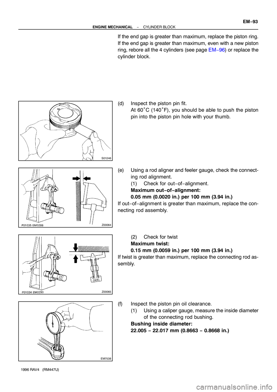
(d) Inspect the piston pin fit.
At 60°C (140°F), you should be able to push the piston
pin into the piston pin hole with your thumb.
(e) Using a rod aligner and feeler gauge, check the connect-
ing rod alignment.
(1) Check for out−of−alignment.
Maximum out−of−alignment:
0.05 mm (0.0020 in.) per 100 mm (3.94 in.)
If out−of−alignment is greater than maximum, replace the con-
necting rod assembly.
(2) Check for twist
Maximum twist:
0.15 mm (0.0059 in.) per 100 mm (3.94 in.)
If twist is greater than maximum, replace the connecting rod as-
sembly.
(f) Inspect the piston pin oil clearance.
(1) Using a caliper gauge, measure the inside diameter
of the connecting rod bushing.
Bushing inside diameter:
22.005 − 22.017 mm (0.8663 − 0.8668 in.)
Page 760 of 1354
EM0227
P13428
P13429
15 mm
(0.59 in.) EM−94
− ENGINE MECHANICALCYLINDER BLOCK
1996 RAV4 (RM447U)
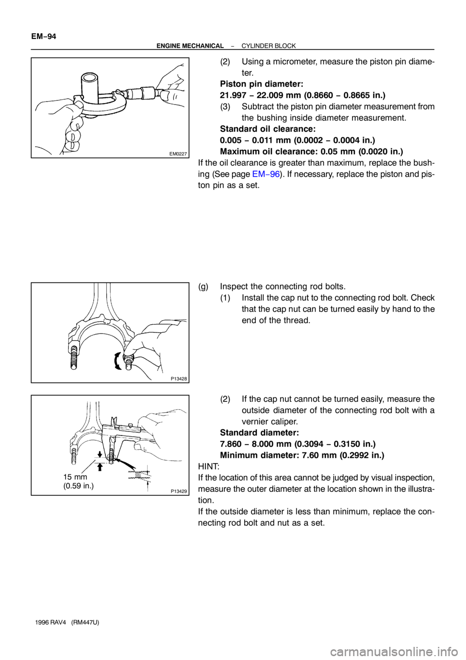
(2) Using a micrometer, measure the piston pin diame-
ter.
Piston pin diameter:
21.997 − 22.009 mm (0.8660 − 0.8665 in.)
(3) Subtract the piston pin diameter measurement from
the bushing inside diameter measurement.
Standard oil clearance:
0.005 − 0.011 mm (0.0002 − 0.0004 in.)
Maximum oil clearance: 0.05 mm (0.0020 in.)
If the oil clearance is greater than maximum, replace the bush-
ing (See page EM−96). If necessary, replace the piston and pis-
ton pin as a set.
(g) Inspect the connecting rod bolts.
(1) Install the cap nut to the connecting rod bolt. Check
that the cap nut can be turned easily by hand to the
end of the thread.
(2) If the cap nut cannot be turned easily, measure the
outside diameter of the connecting rod bolt with a
vernier caliper.
Standard diameter:
7.860 − 8.000 mm (0.3094 − 0.3150 in.)
Minimum diameter: 7.60 mm (0.2992 in.)
HINT:
If the location of this area cannot be judged by visual inspection,
measure the outer diameter at the location shown in the illustra-
tion.
If the outside diameter is less than minimum, replace the con-
necting rod bolt and nut as a set.
Page 761 of 1354
P13414
EM3553
− ENGINE MECHANICALCYLINDER BLOCK
EM−95
1996 RAV4 (RM447U)
5. INSPECT CRANKSHAFT
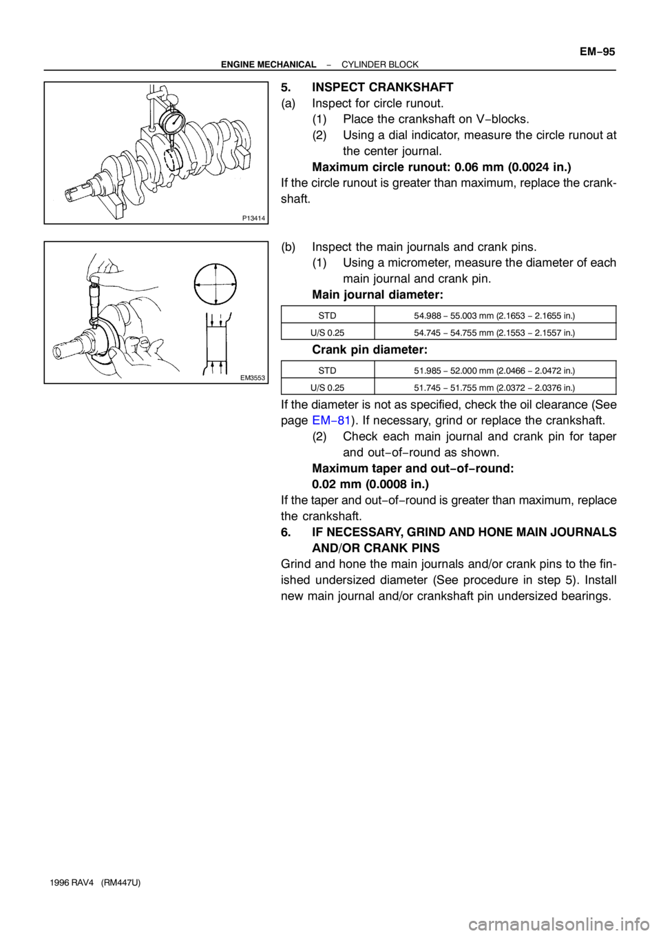
(a) Inspect for circle runout.
(1) Place the crankshaft on V−blocks.
(2) Using a dial indicator, measure the circle runout at
the center journal.
Maximum circle runout: 0.06 mm (0.0024 in.)
If the circle runout is greater than maximum, replace the crank-
shaft.
(b) Inspect the main journals and crank pins.
(1) Using a micrometer, measure the diameter of each
main journal and crank pin.
Main journal diameter:
STD54.988 − 55.003 mm (2.1653 − 2.1655 in.)
U/S 0.2554.745 − 54.755 mm (2.1553 − 2.1557 in.)
Crank pin diameter:
STD51.985 − 52.000 mm (2.0466 − 2.0472 in.)
U/S 0.2551.745 − 51.755 mm (2.0372 − 2.0376 in.)
If the diameter is not as specified, check the oil clearance (See
page EM−81). If necessary, grind or replace the crankshaft.
(2) Check each main journal and crank pin for taper
and out−of−round as shown.
Maximum taper and out−of−round:
0.02 mm (0.0008 in.)
If the taper and out−of−round is greater than maximum, replace
the crankshaft.
6. IF NECESSARY, GRIND AND HONE MAIN JOURNALS
AND/OR CRANK PINS
Grind and hone the main journals and/or crank pins to the fin-
ished undersized diameter (See procedure in step 5). Install
new main journal and/or crankshaft pin undersized bearings.
Page 762 of 1354
EM1Q2−01
EM1321
SST
EM7329
Oil Hole
P01038
EM1322
EM−96
− ENGINE MECHANICALCYLINDER BLOCK
1996 RAV4 (RM447U)
REPLACEMENT
1. REPLACE CONNECTING ROD BUSHINGS
(a) Using SST and a press, press out the bushing.
SST 09222−30010
(b) Align the oil holes of a new bushing and the connecting
rod.
(c) Using SST and a press, press in the bushing.
SST 09222−30010
(d) Using a pin hole grinder, hone the bushing to obtain the
standard specified clearance (See page EM−89) be-
tween the bushing and piston pin.
(e) Check the piston pin fit at normal room temperature. Coat
the piston pin with engine oil, and push it into the connect-
ing rod with your thumb.
2. REPLACE OVERSIZED (O/S) PISTONS FOR CYLIN-
DER BORING
HINT:
�Bore all the 4 cylinders for the O/S piston outside diame-
ter.
�Replace all the piston rings with ones to match the O/S
pistons.
(a) Keep 4 new O/S pistons.
O/S 0.50 piston diameter:
86.370 − 86.400 mm (3.4004 − 3.4016 in.)
Page 763 of 1354
Z11709
26 mm
(1.02 in.)
P05299
P05301
SST
Z00072
Cut Position
− ENGINE MECHANICALCYLINDER BLOCK
EM−97
1996 RAV4 (RM447U)
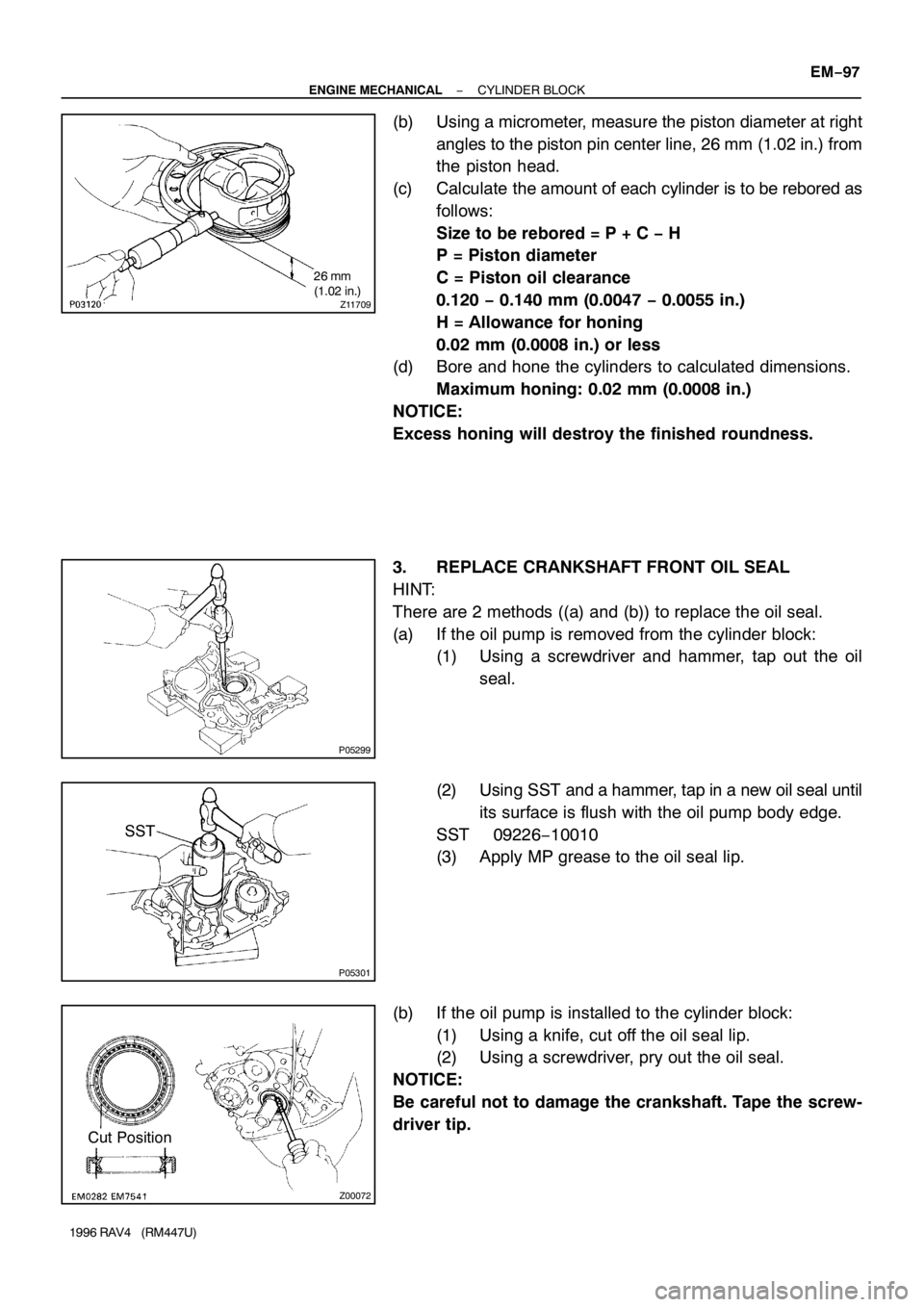
(b) Using a micrometer, measure the piston diameter at right
angles to the piston pin center line, 26 mm (1.02 in.) from
the piston head.
(c) Calculate the amount of each cylinder is to be rebored as
follows:
Size to be rebored = P + C − H
P = Piston diameter
C = Piston oil clearance
0.120 − 0.140 mm (0.0047 − 0.0055 in.)
H = Allowance for honing
0.02 mm (0.0008 in.) or less
(d) Bore and hone the cylinders to calculated dimensions.
Maximum honing: 0.02 mm (0.0008 in.)
NOTICE:
Excess honing will destroy the finished roundness.
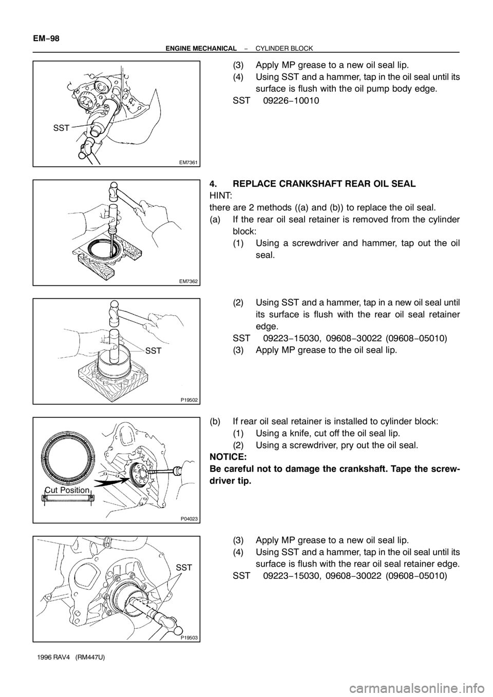
3. REPLACE CRANKSHAFT FRONT OIL SEAL
HINT:
There are 2 methods ((a) and (b)) to replace the oil seal.
(a) If the oil pump is removed from the cylinder block:
(1) Using a screwdriver and hammer, tap out the oil
seal.
(2) Using SST and a hammer, tap in a new oil seal until
its surface is flush with the oil pump body edge.
SST 09226−10010
(3) Apply MP grease to the oil seal lip.
(b) If the oil pump is installed to the cylinder block:
(1) Using a knife, cut off the oil seal lip.
(2) Using a screwdriver, pry out the oil seal.
NOTICE:
Be careful not to damage the crankshaft. Tape the screw-
driver tip.
Page 764 of 1354
EM7361
SST
EM7362
P19502
SST
P04023
Cut Position
P19503
SST EM−98
− ENGINE MECHANICALCYLINDER BLOCK
1996 RAV4 (RM447U)
(3) Apply MP grease to a new oil seal lip.
(4) Using SST and a hammer, tap in the oil seal until its
surface is flush with the oil pump body edge.
SST 09226−10010
4. REPLACE CRANKSHAFT REAR OIL SEAL
HINT:
there are 2 methods ((a) and (b)) to replace the oil seal.
(a) If the rear oil seal retainer is removed from the cylinder
block:
(1) Using a screwdriver and hammer, tap out the oil
seal.
(2) Using SST and a hammer, tap in a new oil seal until
its surface is flush with the rear oil seal retainer
edge.
SST 09223−15030, 09608−30022 (09608−05010)
(3) Apply MP grease to the oil seal lip.
(b) If rear oil seal retainer is installed to cylinder block:
(1) Using a knife, cut off the oil seal lip.
(2) Using a screwdriver, pry out the oil seal.
NOTICE:
Be careful not to damage the crankshaft. Tape the screw-
driver tip.
(3) Apply MP grease to a new oil seal lip.
(4) Using SST and a hammer, tap in the oil seal until its
surface is flush with the rear oil seal retainer edge.
SST 09223−15030, 09608−30022 (09608−05010)
Page 765 of 1354
EM1BD−02
S01247
Front Mark
(Cavity)
Front Mark
(Protrusion)
Z17148
Code Mark
No. 1
No. 2Code Mark
S01227
Upper Side Rail
Expander
No. 2
Compression
RingLower Side
Rail No. 1 Compression
Ring
Front Mark
(Cavity)
P00797
− ENGINE MECHANICALCYLINDER BLOCK
EM−99
1996 RAV4 (RM447U)
REASSEMBLY
HINT:
�Thoroughly clean all parts to be assembled.
�Before installing the parts, apply new engine oil to all slid-
ing and rotating surfaces.
�Replace all gaskets, O−rings and oil seals with new parts.
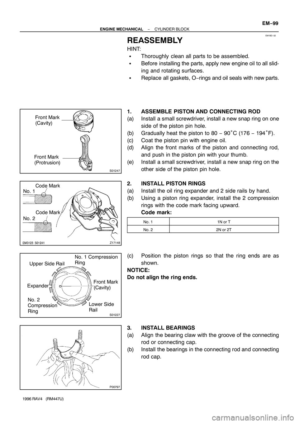
1. ASSEMBLE PISTON AND CONNECTING ROD
(a) Install a small screwdriver, install a new snap ring on one
side of the piston pin hole.
(b) Gradually heat the piston to 80 − 90°C (176 − 194°F).
(c) Coat the piston pin with engine oil.
(d) Align the front marks of the piston and connecting rod,
and push in the piston pin with your thumb.
(e) Install a small screwdriver, install a new snap ring on the
other side of the piston pin hole.
2. INSTALL PISTON RINGS
(a) Install the oil ring expander and 2 side rails by hand.
(b) Using a piston ring expander, install the 2 compression
rings with the code mark facing upward.
Code mark:
No. 11N or T
No. 22N or 2T
(c) Position the piston rings so that the ring ends are as
shown.
NOTICE:
Do not align the ring ends.
3. INSTALL BEARINGS
(a) Align the bearing claw with the groove of the connecting
rod or connecting cap.
(b) Install the bearings in the connecting rod and connecting
rod cap.
Page 766 of 1354
P05533
No.3 Others
22.9 mm19.2 mm
P05353
P03177
Mark
1, 2, 3, 4 or 5
P05354
P03173
EM−100
− ENGINE MECHANICALCYLINDER BLOCK
1996 RAV4 (RM447U)
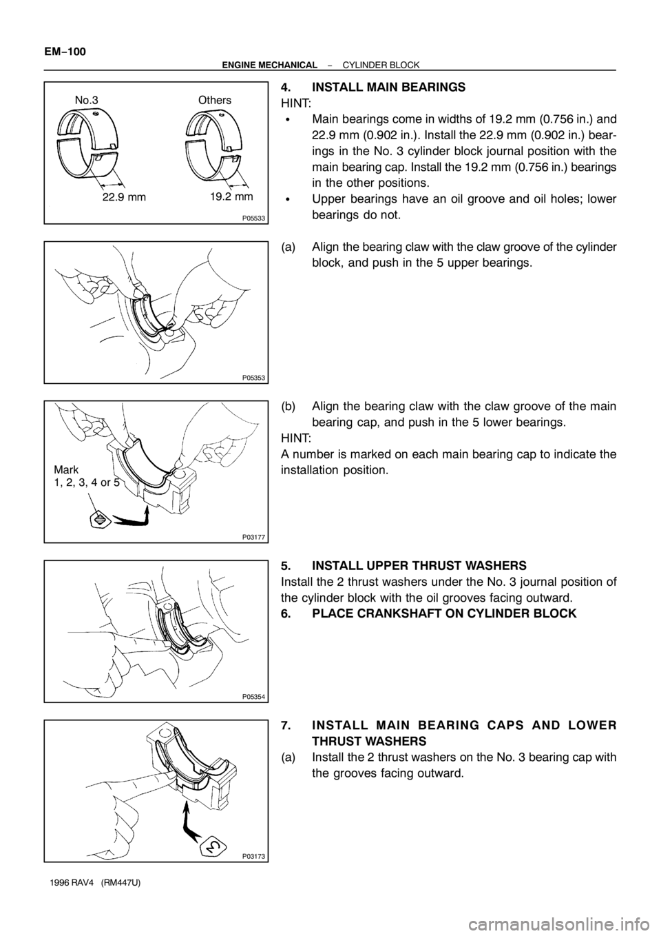
4. INSTALL MAIN BEARINGS
HINT:
�Main bearings come in widths of 19.2 mm (0.756 in.) and
22.9 mm (0.902 in.). Install the 22.9 mm (0.902 in.) bear-
ings in the No. 3 cylinder block journal position with the
main bearing cap. Install the 19.2 mm (0.756 in.) bearings
in the other positions.
�Upper bearings have an oil groove and oil holes; lower
bearings do not.
(a) Align the bearing claw with the claw groove of the cylinder
block, and push in the 5 upper bearings.
(b) Align the bearing claw with the claw groove of the main
bearing cap, and push in the 5 lower bearings.
HINT:
A number is marked on each main bearing cap to indicate the
installation position.
5. INSTALL UPPER THRUST WASHERS
Install the 2 thrust washers under the No. 3 journal position of
the cylinder block with the oil grooves facing outward.
6. PLACE CRANKSHAFT ON CYLINDER BLOCK
7. INSTALL MAIN BEARING CAPS AND LOWER
THRUST WASHERS
(a) Install the 2 thrust washers on the No. 3 bearing cap with
the grooves facing outward.