Page 998 of 1354

MX−3
1996 RAV4 (RM447U)
REMOVAL
1. REMOVE AIR CLEANER CASE ASSEMBLY WITH AIR
HOSE
2. REMOVE ENGINE")
MX05O−02
Q08747
Q08748
A
B
Q08749
Q08750
A B
A
− MANUAL TRANSAXLEMANUAL TRANSAXLE UNIT (2WD)
MX−3
1996 RAV4 (RM447U)
REMOVAL
1. REMOVE AIR CLEANER CASE ASSEMBLY WITH AIR
HOSE
2. REMOVE ENGINE COOLANT RESERVOIR TANK
3. REMOVE ENGINE WIRE CLAMP SET NUT
4. REMOVE STARTER
(a) Disconnect the connector and wire from the starter.
(b) Remove the 2 bolts and starter.
Torque: 39 N·m (400 kgf·cm, 29 ft·lbf)
5. DISCONNECT CLUTCH RELEASE CYLINDER AND
LINE
(a) Remove the 2 set bolts of the clutch line bracket.
Torque:
Bolt A: 12 N·m (120 kgf·cm, 9 ft·lbf)
Bolt B: 4.9 N·m (50 kgf·cm, 43 in.·lbf)
(b) Remove the 2 bolts, release cylinder and line.
Torque: 12 N·m (120 kgf·cm, 9 ft·lbf)
6. DISCONNECT GROUND CABLE
Remove the set bolt of the ground cable from the transaxle.
7. DISCONNECT VEHICLE SPEED SENSOR AND
BACK−UP LIGHT SWITCH CONNECTORS
8. DISCONNECT CONTROL CABLE
(a) Remove the 2 clips and washers.
(b) Remove the 2 clips from the cables.
9. REMOVE 4 TRANSAXLE UPPER SIDE MOUNTING
BOLTS
Torque:
Bolt A: 64 N·m (650 kgf·cm, 47 ft·lbf)
Bolt B: 35 N·m (360 kgf·cm, 26 ft·lbf)
Page 1003 of 1354
MX05R−02
Q09030
Solenoid Hose No.1
Transfer Vacuum Actuator
Bracket
Transfer Vacuum Actuator Assembly
Right Transfer Stiffener Plate
Center Transfer Stiffener Plate
Differential Lock Indicator Switch Connector
Back−Up Light
Switch Connector
Vehicle Speed
Sensor Connector
Transaxle Case Protector
Starter Stiffener Plate
N·m (kgf·cm, ft·lbf): Specified torque
25 (250, 18)
37 (380, 27)
9.0 (95, 78 in.·lbf)
37 (380, 27)
37 (380, 27)
37 (380, 27)
37 (380, 27)
37 (380, 27)
37 (380, 27)
37 (380, 27)
37 (380, 27)
37 (380, 27)
46 (470, 34)
29 (300, 22)
25 (250, 18)
64 (650, 47)
39 (400, 29)
64 (650, 47)
35 (360, 26)
29 (300, 22)
Solenoid Hose No.0
Solenoid Hose No.2
Solenoid Hose No.0 MX−8
− MANUAL TRANSAXLEMANUAL TRANSAXLE UNIT (4WD)
1996 RAV4 (RM447U)
MANUAL TRANSAXLE UNIT (4WD)
COMPONENTS
Page 1004 of 1354

MX−9
1996 RAV4 (RM447U)
REMOVAL
1. REMOVE TRANSAXLE WITH ENGINE
(See page EM−80)
2. R")
MX05S−01
Q09031
B
A
C
FED A
A
C
Q08759
No.1
No.2 No.0
No.0
− MANUAL TRANSAXLEMANUAL TRANSAXLE UNIT (4WD)
MX−9
1996 RAV4 (RM447U)
REMOVAL
1. REMOVE TRANSAXLE WITH ENGINE
(See page EM−80)
2. REMOVE TRANSAXLE CASE PROTECTOR
Remove the 2 bolts and transaxle case protector.
Torque: 25 N·m (250 kgf·cm, 18 ft·lbf)
3. REMOVE STARTER
(a) Disconnect the connector and wire from the starter.
(b) Remove the 2 bolts and starter.
Torque: 39 N·m (400 kgf·cm, 29 ft·lbf)
4. DISCONNECT DIFFERENTIAL LOCK INDICATOR
SWITCH, BACK−UP LIGHT SWITCH AND VEHICLE
SPEED SENSOR CONNECTORS
5. REMOVE TRANSFER VACUUM ACTUATOR BRACK-
ET
Remove the 4 bolts and bracket.
Torque: 37 N·m (380 kgf·cm, 27 ft·lbf)
6. REMOVE TRANSFER VACUUM ACTUATOR AS-
SEMBLY
(a) Disconnect the 4 solenoid hoses from the transfer vacu-
um actuator assembly.
NOTICE:
At the time of installation, please refer to the following item.
Check that the hose No.0, No.1 and No.2 are securely
installed to the solenoid.
(b) Remove the 2 bolts and transfer vacuum actuator assem-
bly.
Torque: 37 N·m (380 kgf·cm, 27 ft·lbf)
7. REMOVE RIGHT TRANSFER STIFFENER PLATE
Remove the 5 bolts and right transfer stiffener plate.
Torque: 37 N·m (380 kgf·cm, 27 ft·lbf)
8. REMOVE CENTER TRANSFER STIFFENER PLATE
Remove the 3 bolts and center transfer stiffener plate.
Torque: 37 N·m (380 kgf·cm, 27 ft·lbf)
9. REMOVE STIFFENER PLATE
Remove the 2 bolts and stiffener plate.
Torque: 37 N·m (380 kgf·cm, 27 ft·lbf)
10. REMOVE TRANSAXLE FROM ENGINE
(a) Remove the 9 transaxle mounting bolts from the engine.
Torque:
Bolt A: 64 N·m (650 kgf·cm, 47 ft·lbf)
Bolt B: 35 N·m (360 kgf·cm, 26 ft·lbf)
Bolt C: 29 N·m (300 kgf·cm, 22 ft·lbf)
Bolt D: 46 N·m (470 kgf·cm, 34 ft·lbf)
Bolt E: 25 N·m (250 kgf·cm, 18 ft·lbf)
Bolt F: 9.0 N·m (95 kgf·cm, 78 in.·lbf)
Page 1007 of 1354
MX05U−01
Q09032
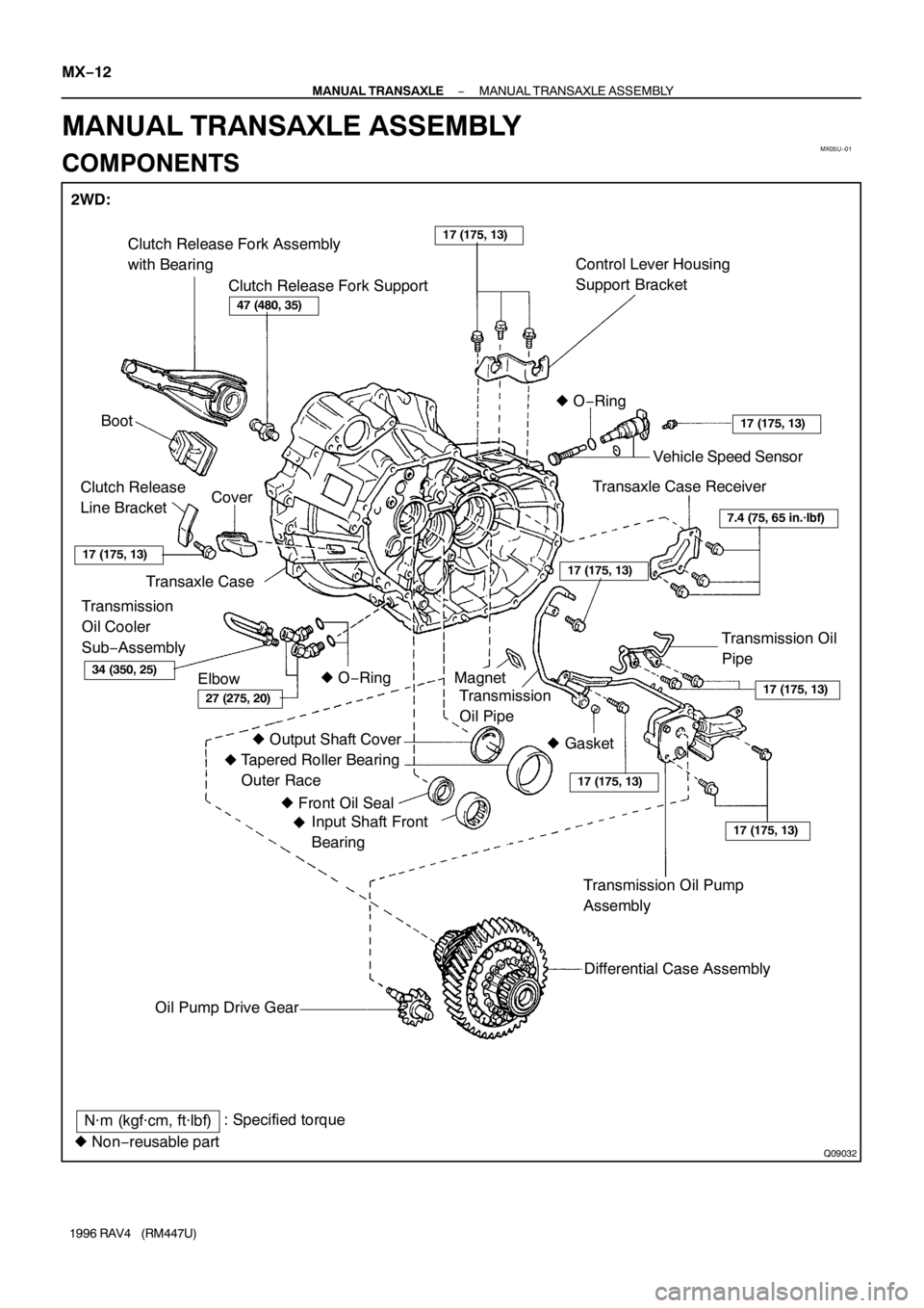
2WD:
Clutch Release Fork Assembly
with Bearing
Clutch Release Fork SupportControl Lever Housing
Support Bracket
Boot� O−Ring
Cover Clutch Release
Line Bracket
Transaxle Case
Transmission
Oil Cooler
Sub−Assembly
Elbow� O−RingVehicle Speed Sensor
Transaxle Case Receiver
Transmission Oil
Pipe
Magnet
Transmission
Oil Pipe
� Output Shaft Cover
Tapered Roller Bearing
Outer Race
� Front Oil Seal
Input Shaft Front
Bearing
Transmission Oil Pump
Assembly
Differential Case Assembly
Oil Pump Drive Gear
17 (175, 13)
47 (480, 35)
34 (350, 25)
27 (275, 20)
7.4 (75, 65 in.·lbf)
17 (175, 13)
17 (175, 13)
17 (175, 13)
17 (175, 13)
17 (175, 13)
17 (175, 13)
N·m (kgf·cm, ft·lbf): Specified torque
� Non−reusable part� Gasket
� � MX−12
− MANUAL TRANSAXLEMANUAL TRANSAXLE ASSEMBLY
1996 RAV4 (RM447U)
MANUAL TRANSAXLE ASSEMBLY
COMPONENTS
Page 1008 of 1354
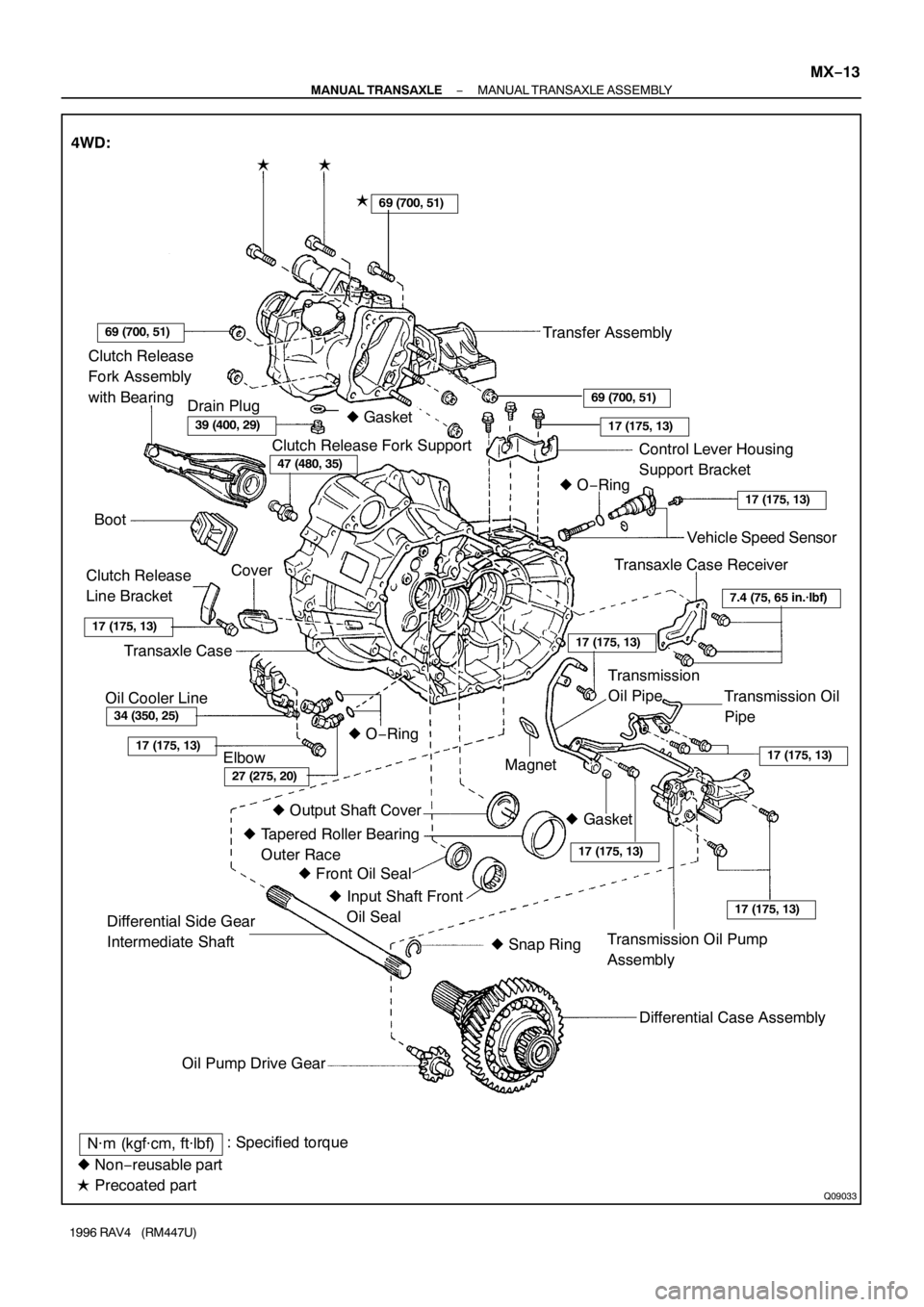
Q09033
Clutch Release
Fork Assembly
with Bearing
Clutch Release Fork Support
Control Lever Housing
Support Bracket
Boot� O−Ring
Cover
Clutch Release
Line Bracket
Transaxle Case
Elbow� O−RingVehicle Speed Sensor
Transaxle Case Receiver
Transmission Oil
Pipe
Magnet
� Output Shaft Cover
� Tapered Roller Bearing
Outer Race
� Front Oil Seal
� Input Shaft Front
Oil Seal
Transmission Oil Pump
Assembly
Differential Case Assembly
Oil Pump Drive Gear
34 (350, 25)
27 (275, 20)
7.4 (75, 65 in.·lbf)
17 (175, 13)
17 (175, 13)
17 (175, 13)
17 (175, 13)
17 (175, 13)
17 (175, 13)
N·m (kgf·cm, ft·lbf): Specified torque
� Non−reusable part
� Precoated part 4WD:
�
�
Transfer Assembly
Transmission
Oil Pipe
17 (175, 13)
17 (175, 13)
69 (700, 51)
69 (700, 51)
39 (400, 29)
47 (480, 35)
Differential Side Gear
Intermediate Shaft
� Snap Ring
69 (700, 51)
Drain Plug
Oil Cooler Line� Gasket
� Gasket �
− MANUAL TRANSAXLEMANUAL TRANSAXLE ASSEMBLY
MX−13
1996 RAV4 (RM447U)
Page 1011 of 1354

DISASSEMBLY
1. 4WD:
REMOVE TRANSFER ASSEMBLY
(a) Remove the 3 bolts.
Sealant")
MX05V−02
Q08757
FIPG
Z12375SST
Q09043
255.5 mm MX−16
− MANUAL TRANSAXLEMANUAL TRANSAXLE ASSEMBLY
1996 RAV4 (RM447U)
DISASSEMBLY
1. 4WD:
REMOVE TRANSFER ASSEMBLY
(a) Remove the 3 bolts.
Sealant:
Part No. 08833−00080, THREE BOND 1344, LOCTITE
242 or equivalent
Torque: 69 N·m (700 kgf·cm, 51 ft·lbf)
(b) Remove the 5 nuts.
Torque: 69 N·m (700 kgf·cm, 51 ft·lbf)
(c) Using a plastic hammer, remove the transfer assembly
from the transaxle.
HINT:
At the time of reassembly, please refer to the following item.
Shift into the 4th gear, and install the transfer assembly while
turning the input shaft of the transaxle.
FIPG:
Part No. 08826−00090, THREE BOND 1281 or equiva-
lent
2. 4WD:
REMOVE DIFFERENTIAL SIDE GEAR INTERMEDI-
ATE SHAFT
(a) Screw in a suitable bolt with a washer into the side gear
intermediate shaft.
(b) Using SST, remove the side gear intermediate shaft.
SST 09910−00015 (09911−00011, 09912−00010)
(c) Remove the snap ring from the differential side gear inter-
mediate shaft.
HINT:
At the time of reassembly, please refer to the following item.
Keeping the intermediate shaft on the differential pinion shaft,
measure the dimension, as shown in the illustration.
Protrusion length: 255.5 mm (10.06 in.)
3. REMOVE RELEASE FORK AND BEARING
4. REMOVE BACK−UP LIGHT SWITCH WITH GASKET
Torque: 40 N·m (410 kgf·cm, 30 ft·lbf)
5. REMOVE BOLT AND VEHICLE SPEED SENSOR
Torque: 17 N·m (175 kgf·cm, 13 ft·lbf)
6. REMOVE NO.2 SELECTING BELLCRANK WITH SE-
LECTING BELLCRANK SUPPORT
Remove the 2 bolts and No.2 selecting bellcrank with the se-
lecting bellcrank support.
Sealant:
Part No. 08833−00080, THREE BOND 1344, LOCTITE
242 or equivalent
Torque: 20 N·m (200 kgf·cm, 14 ft·lbf)
Page 1044 of 1354
MX060−01
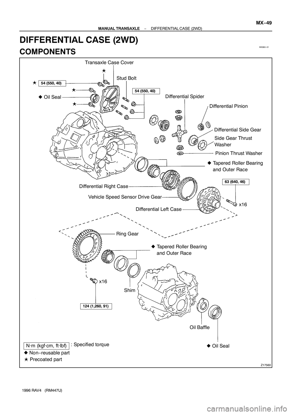
Z17560
Transaxle Case Cover
Differential Spider
Differential Pinion
Differential Side Gear
Side Gear Thrust
Washer
Pinion Thrust Washer
� Tapered Roller Bearing
and Outer Race
Differential Right Case
Vehicle Speed Sensor Drive Gear
Differential Left Case
� Tapered Roller Bearing
and Outer Race Ring Gear
Oil Baffle
� Oil Seal x16
Shim � Oil Seal
54 (550, 40)
63 (640, 46)
N·m (kgf·cm, ft·lbf): Specified torque
� Non−reusable part� ��
�
x16
� Precoated partStud Bolt
54 (550, 40)
124 (1,260, 91)
− MANUAL TRANSAXLEDIFFERENTIAL CASE (2WD)
MX−49
1996 RAV4 (RM447U)
DIFFERENTIAL CASE (2WD)
COMPONENTS
Page 1045 of 1354
Q05166
SST
MX0DV−01
Z00281
Matchmarks
Z00284
MX−50
− MANUAL TRANSAXLEDIFFERENTIAL CASE (2WD)
1996 RAV4 (RM447U)
DISASSEMBLY
1. REMOVE TAPERED ROLLER BEARING
Using SST, remove the left and right bearings.
SST 09950−40010
2. REMOVE RING GEAR
(a) Place matchmarks on both the differential case and ring
gear.
(b) Remove the 16 bolts.
(c) Using a plastic hammer, tap the ring gear and remove it.
3. DISASSEMBLE DIFFERENTIAL CASE
(a) Place matchmarks on the differential right and left cases.
(b) Using a torx wrench (T50), remove the 16 torx screws.
(c) Using a plastic hammer, tap the differential left case.
(d) Remove the vehicle speed sensor drive gear from the dif-
ferential right case.
(e) Remove the 2 differential side gears, side gear thrust
washers, 4 differential pinions and pinion thrust washers
from the differential left case.


1996 RAV4 (RM447U)
DISASSEMBLY
1. REMOVE TAPERED ROLLER BEARING
Using SST, remove the left and righ")