Page 1176 of 1354

R10041
SST
SA0UC−03
R10773Matchmarks SA−62
− SUSPENSION AND AXLEREAR DRIVE SHAFT
1996 RAV4 (RM447U)
REMOVAL
NOTICE:
�The hub bearing could be damaged if it is subjected
to the vehicle weight, such as when moving the ve-
hicle with the drive shaft bearing removed. Therefore,
if it is absolutely necessary to place the vehicle
weight on the hub bearing, first support it with SST.
SST 09608−16042 (09608−02021, 09608−02041)
�w/ ABS:
After disconnecting the drive shaft from the axle hub,
work carefully so as not to damage the sensor rotor
serrations on the drive shaft.
1. REMOVE REAR WHEEL
Torque: 103 N·m (1,050 kgf·cm, 76 ft·lbf)
2. w/ ABS:
REMOVE BOLT AND ABS SPEED SENSOR
Torque: 7.8 N·m (80 kgf·cm, 69 ft·lbf)
3. REMOVE DRIVE SHAFT LOCK NUT
(a) Remove the cotter pin and lock cap.
(b) With depressing the brakes, remove the nut.
Torque: 206 N·m (2,100 kgf·cm, 152 ft·lbf)
4. REMOVE DRIVE SHAFT
(a) Place matchmarks on the drive shaft and differential side
gear shaft.
(b) Remove the 4 nuts and washers, and disconnect the
drive shaft from the differential side gear shaft.
Torque: 56 N·m (570 kgf·cm, 41 ft·lbf)
(c) Remove the drive shaft from the axle carrier.
Page 1179 of 1354

SA0UE−05
F01439
w/o ABS w/ ABS
SST
RA1310
Vinyl Tape
− SUSPENSION AND AXLEREAR DRIVE SHAFT
SA−65
1996 RAV4 (RM447U)
REASSEMBLY
1. INSTALL NEW NO.2 DUST DEFLECTOR
Using SST and a press, install a new No.2 dust deflector.
SST 09309−36010, 09316−20011
NOTICE:
Be careful not to damage the ABS speed sensor rotor.
2. TEMPORARILY INSTALL NEW OUTBOARD AND IN-
BOARD JOINT BOOTS
HINT:
Before installing the 2 boots, wrap vinyl tape around the spline
of the drive shaft to prevent damaging the boots.
(a) Temporarily install a new outboard joint boot to the drive
shaft.
(b) Temporarily install a new inboard joint boot to the drive
shaft.
3. INSTALL TRIPOD
(a) Place the beveled side of the tripod axial spline toward the
outboard joint.
(b) Align the matchmarks placed before removal.
(c) Using a brass bar and hammer, tap in the tripod to the
drive shaft.
NOTICE:
Do not tap the roller.
(d) Using a snap ring expander, install a new snap ring.
4. INSTALL INBOARD JOINT TULIP
(a) Pack the inboard joint and boot with grease in the boot kit.
HINT:
Use the grease supplied in the boot kit.
Grease capacity (Color = Yellow ocher):
180 − 190 g (6.3 − 6.7 oz.)
(b) Align the matchmarks placed before removal, and install
the inboard joint tulip to the drive shaft.
5. ASSEMBLE BOOT CLAMPS TO BOTH BOOTS
(a) Before assembling the boot, pack the outboard joint and
boot with grease in the boot kit.
Use the grease supplied in the boot kit.
Grease capacity (Color = Black):
100 − 110 g (3.5 − 3.9 oz.)
(b) Make sure that the 2 boots are on the shaft groove.
Page 1181 of 1354
SA0UF−07
− SUSPENSION AND AXLEREAR DRIVE SHAFT
SA−67
1996 RAV4 (RM447U)
INSTALLATION
Installation is in the reverse order of removal (See page SA−62).
AFTER INSTALLATION, CHECK ABS SPEED SENSOR SIGNAL (See page DI−257)
Page 1210 of 1354

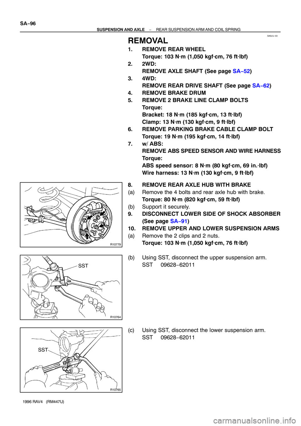
SA0UU−03
R10779
R10764
SST
R10765
SST SA−96
− SUSPENSION AND AXLEREAR SUSPENSION ARM AND COIL SPRING
1996 RAV4 (RM447U)
REMOVAL
1. REMOVE REAR WHEEL
Torque: 103 N·m (1,050 kgf·cm, 76 ft·lbf)
2. 2WD:
REMOVE AXLE SHAFT (See page SA−52)
3. 4WD:
REMOVE REAR DRIVE SHAFT (See page SA−62)
4. REMOVE BRAKE DRUM
5. REMOVE 2 BRAKE LINE CLAMP BOLTS
Torque:
Bracket: 18 N·m (185 kgf·cm, 13 ft·lbf)
Clamp: 13 N·m (130 kgf·cm, 9 ft·lbf)
6. REMOVE PARKING BRAKE CABLE CLAMP BOLT
Torque: 19 N·m (195 kgf·cm, 14 ft·lbf)
7. w/ ABS:
REMOVE ABS SPEED SENSOR AND WIRE HARNESS
Torque:
ABS speed sensor: 8 N·m (80 kgf·cm, 69 in.·lbf)
Wire harness: 13 N·m (130 kgf·cm, 9 ft·lbf)
8. REMOVE REAR AXLE HUB WITH BRAKE
(a) Remove the 4 bolts and rear axle hub with brake.
Torque: 80 N·m (820 kgf·cm, 59 ft·lbf)
(b) Support it securely.
9. DISCONNECT LOWER SIDE OF SHOCK ABSORBER
(See page SA−91)
10. REMOVE UPPER AND LOWER SUSPENSION ARMS
(a) Remove the 2 clips and 2 nuts.
Torque: 103 N·m (1,050 kgf·cm, 76 ft·lbf)
(b) Using SST, disconnect the upper suspension arm.
SST 09628−62011
(c) Using SST, disconnect the lower suspension arm.
SST 09628−62011
Page 1214 of 1354
SA0UX−04
SA−100
− SUSPENSION AND AXLEREAR SUSPENSION ARM AND COIL SPRING
1996 RAV4 (RM447U)
INSTALLATION
Installation is in the reverse order of removal (See page SA−96).
AFTER INSTALLATION, CHECK ABS SPEED SENSOR SIGNAL (See page DI−257) AND REAR WHEEL
ALIGNMENT (See page SA−7)
Page 1241 of 1354

S01898
SF0QO−03
S01946
P
E
R
S00037
Ohmmeter
Throttle Position Sensor
VC
VTA
E2
S01901
Disconnect
Plug
− SFITHROTTLE BODY
SF−27
1996 RAV4 (RM447U)
THROTTLE BODY
ON−VEHICLE INSPECTION
1. INSPECT THROTTLE BODY
(a) Check that the throttle linkage moves smoothly.
(b) Check the vacuum at each port.
�Start the engine.
�Check the vacuum with your finger.
Port nameAt idleOther than idle
PNo vacuumVacuum
ENo vacuumVacuum
RNo vacuumNo vacuum
2. INSPECT THROTTLE POSITION SENSOR
(a) Apply vacuum to the throttle opener.
(b) Disconnect the sensor connector.
(c) Using an ohmmeter, measure the resistance between
each terminal.
Clearance between
lever and stop screwBetween
terminalsResistance
0 mm (0 in.)VTA − E20.2 − 5.7 kΩ
Throttle valve fully
openVTA − E22.0 − 10.2 kΩ
−VC − E22.5 − 5.9 kΩ
(d) Reconnect the sensor connector.
3. INSPECT AND ADJUST THROTTLE OPENER
4. WARM UP ENGINE
Allow the engine to warm up to normal operating temperature.
5. CHECK IDLE SPEED
Idle speed: 700 ± 50 rpm
6. CHECK AND ADJUST THROTTLE OPENER SETTING
SPEED
(a) Disconnect the vacuum hose from the throttle opener,
and plug the hose end.
(b) Maintain the engine at 2,500 rpm.
(c) Release the throttle valve.
(d) Check that the throttle opener is set.
Throttle opener setting speed:
1,300 − 1,500 rpm (w/ cooling fan OFF)