Page 1367 of 1399

Z18976
B
Z18977
C
TR−6
−
TRANSFER TRANSFER ASSEMBLY
1996 LAND CRUISER (RM451U)
11. REMOVE RETAINER FROM REAR CASE
Remove the 5 bolts and retainer.
Torque: 39 N·m (400 kgf·cm, 28 ft·lbf)
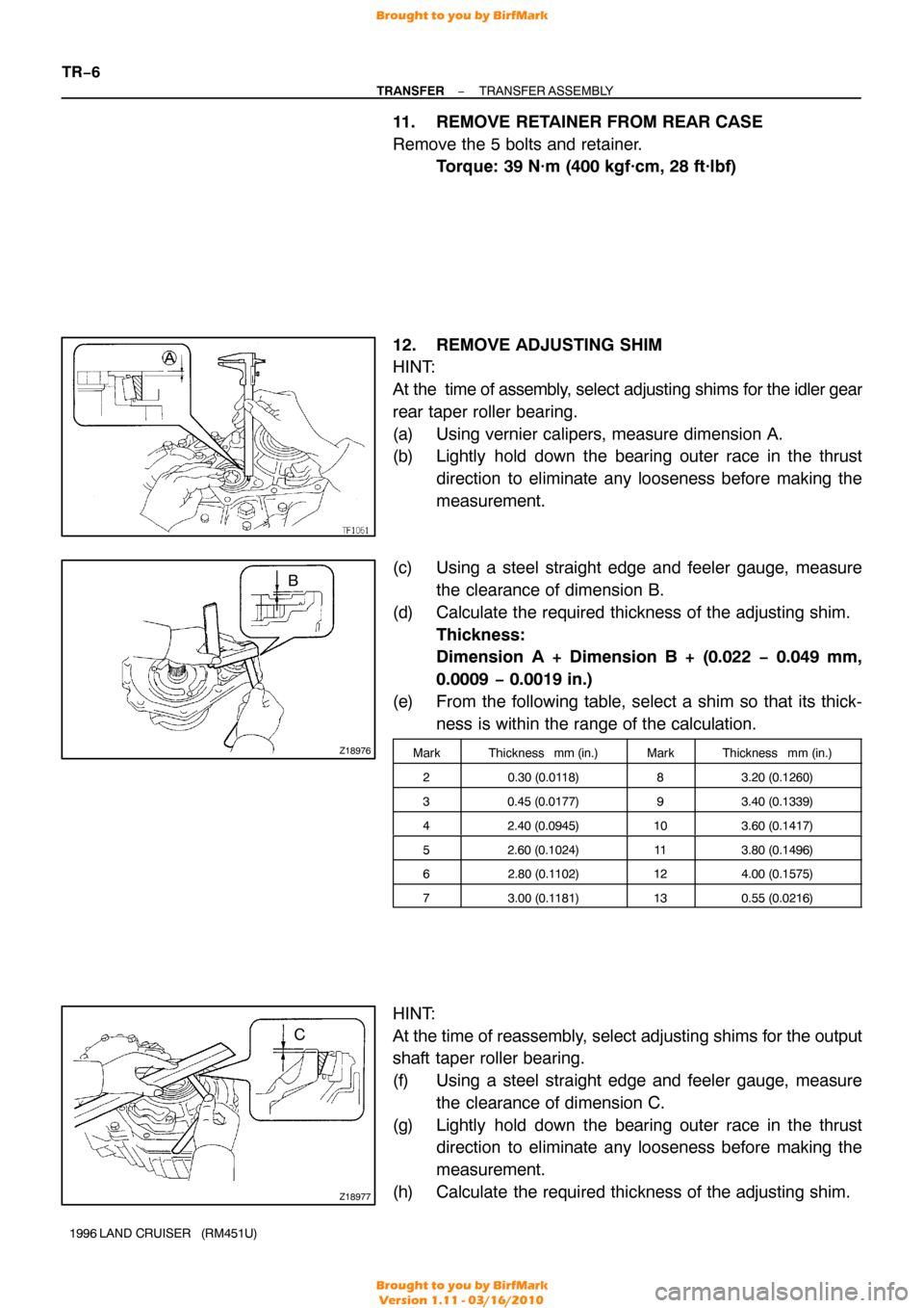
12. REMOVE ADJUSTING SHIM
HINT:
At the time of assembly, select adjusting shims for the idler gear
rear taper roller bearing.
(a) Using vernier calipers, measure dimension A.
(b) Lightly hold down the bearing outer race in the thrust direction to eliminate any looseness before making the
measurement.
(c) Using a steel straight edge and feeler gauge, measure the clearance of dimension B.
(d) Calculate the required thickness of the adjusting shim. Thickness:
Dimension A + Dimension B + (0.022 − 0.049 mm,
0.0009 − 0.0019 in.)
(e) From the following table, select a shim so that its thick- ness is within the range of the calculation.
MarkThickness mm (in.)MarkThickness mm (in.)
20.30 (0.0118)83.20 (0.1260)
30.45 (0.0177)93.40 (0.1339)
42.40 (0.0945)103.60 (0.1417)
52.60 (0.1024)113.80 (0.1496)
62.80 (0.1 102)124.00 (0.1575)
73.00 (0.1181)130.55 (0.0216)
HINT:
At the time of reassembly, select adjusting shims for the output
shaft taper roller bearing.
(f) Using a steel straight edge and feeler gauge, measure
the clearance of dimension C.
(g) Lightly hold down the bearing outer race in the thrust direction to eliminate any looseness before making the
measurement.
(h) Calculate the required thickness of the adjusting shim.
Brought to you by BirfMark
Brought to you by BirfMark
Version 1.11 - 03/16/2010
Page 1369 of 1399

TF0854
TF0986
TF0857
Q07130
RemovalInstallation
Socket Wrench Socket Wrench
TR−8
−
TRANSFER TRANSFER ASSEMBLY
1996 LAND CRUISER (RM451U)
FIPG: Part No. 08826−00090, THREE BOND 1281 or
equivalent
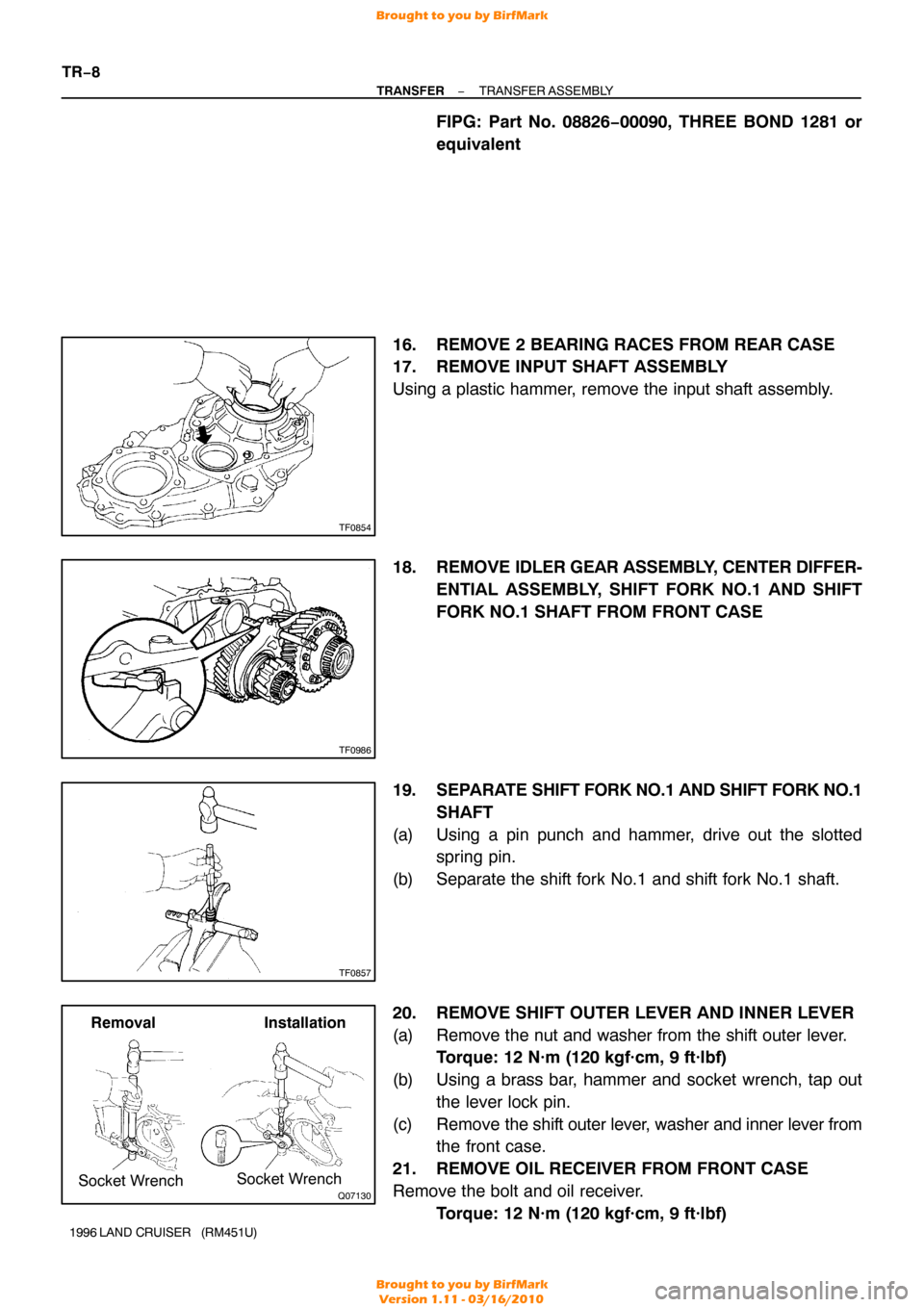
16. REMOVE 2 BEARING RACES FROM REAR CASE
17. REMOVE INPUT SHAFT ASSEMBLY
Using a plastic hammer, remove the input shaft assembly.
18. REMOVE IDLER GEAR ASSEMBLY, CENTER DIFFER-
ENTIAL ASSEMBLY, SHIFT FORK NO.1 AND SHIFT
FORK NO.1 SHAFT FROM FRONT CASE
19. SEPARATE SHIFT FORK NO.1 AND SHIFT FORK NO.1 SHAFT
(a) Using a pin punch and hammer, drive out the slotted spring pin.
(b) Separate the shift fork No.1 and shift fork No.1 shaft.
20. REMOVE SHIFT OUTER LEVER AND INNER LEVER
(a) Remove the nut and washer from the shift outer lever. Torque: 12 N·m (120 kgf·cm, 9 ft·lbf)
(b) Using a brass bar, hammer and socket wrench, tap out the lever lock pin.
(c) Remove the shift outer lever, washer and inner lever from
the front case.
21. REMOVE OIL RECEIVER FROM FRONT CASE
Remove the bolt and oil receiver. Torque: 12 N·m (120 kgf·cm, 9 ft·lbf)
Brought to you by BirfMark
Brought to you by BirfMark
Version 1.11 - 03/16/2010
Page 1374 of 1399
TR0B6−01
TF0870
Socket
Wrench
−
TRANSFER INPUT SHAFT
TR−13
1996 LAND CRUISER (RM451U)
DISASSEMBLY
1. REMOVE REAR BALL BEARING
(a) Using a snap ring expander, remove the snap ring.
(b) Using a socket wrench and press, remove the rear ball
bearing.
2. REMOVE INPUT GEAR
(a) Using a snap ring expander, remove the snap ring.
(b) Using a press, remove the input gear.
3. REMOVE FRONT BALL BEARING
Using a press, remove the front ball bearing.
Brought to you by BirfMark
Brought to you by BirfMark
Version 1.11 - 03/16/2010
Page 1375 of 1399

TR0B7−01
Q00533
TR−14
−
TRANSFER INPUT SHAFT
1996 LAND CRUISER (RM451U)
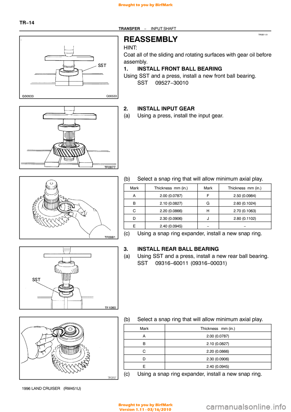
REASSEMBLY
HINT:
Coat all of the sliding and rotating surfaces with gear oil before
assembly.
1. INSTALL FRONT BALL BEARING
Using SST and a press, install a new front ball bearing. SST 09527−30010
2. INSTALL INPUT GEAR
(a) Using a press, install the input gear.
(b) Select a snap ring that will allow minimum axial play.
MarkThickness mm (in.)MarkThickness mm (in.)
A2.00 (0.0787)F2.50 (0.0984)
B2.10 (0.0827)G2.60 (0.1024)
C2.20 (0.0866)H2.70 (0.1063)
D2.30 (0.0906)J2.80 (0.1 102)
E2.40 (0.0945)−−
(c) Using a snap ring expander, install a new snap ring.
3. INSTALL REAR BALL BEARING
(a) Using SST and a press, install a new rear ball bearing.
SST 09316−60011 (09316 −00031)
(b) Select a snap ring that will allow minimum axial play.
MarkThickness mm (in.)
A2.00 (0.0787)
B2.10 (0.0827)
C2.20 (0.0866)
D2.30 (0.0906)
E2.40 (0.0945)
(c) Using a snap ring expander, install a new snap ring.
Brought to you by BirfMark
Brought to you by BirfMark
Version 1.11 - 03/16/2010
Page 1376 of 1399
TR0B8−01
Z15264
Front Taper Roller BearingIdler Gear
High and Low
Clutch SleeveNeedle Roller Bearing
Idler
Low Gear Rear Taper
Roller Bearing
−
TRANSFER IDLER GEAR
TR−15
825
Author�: Date�:
1996 LAND CRUISER (RM451U)
IDLER GEAR
COMPONENTS
Brought to you by BirfMark
Brought to you by BirfMark
Version 1.11 - 03/16/2010
Page 1377 of 1399
TR0B9−01
TF0887
TF0888
Q07132
SST
Q07100
Socket Wrench
TR−16
−
TRANSFER IDLER GEAR
1996 LAND CRUISER (RM451U)
DISASSEMBLY
1. INSPECT IDLER LOW GEAR RADIAL AND THRUST
CLEARANCE
(a) Using a feeler gauge, measure the idler low gear thrust clearance.
Standard clearance:
0.125−0.275 mm (0.0049 −0.0108 in.)
Maximum clearance:
0.275 mm (0.0108 in.)
(b) Using a dial indicator, measure the idler low gear radial clearance.
Standard clearance:
0.015−0.068 mm (0.0006 −0.0027 in.)
Maximum clearance:
0.068 mm (0.0027 in.)
2. REMOVE FRONT TAPER ROLLER BEARING
Using SST, remove the front taper roller bearing. SST 09950−40010
3. REMOVE REAR TAPER ROLLER BEARING
Using SST, a press and socket wrench, remove the rear taper
roller bearing. SST 09950−00020
4. REMOVE IDLER LOW GEAR AND NEEDLE ROLLER BEARING FROM IDLER GEAR
5. REMOVE HIGH AND LOW CLUTCH SLEEVE FROM IDLER GEAR
Brought to you by BirfMark
Brought to you by BirfMark
Version 1.11 - 03/16/2010
Page 1378 of 1399
TR0BA−01
TF0893
SST
Q00538
TF0896
SST
−
TRANSFER IDLER GEAR
TR−17
1996 LAND CRUISER (RM451U)
REASSEMBLY
HINT:
Coat all of the sliding and rotating surfaces with gear oil before
assembly.
1. INSTALL FRONT TAPER ROLLER BEARING
Using SST and a press, install the front taper roller bearing.
SST 09316−60011 (09316 −00011, 09316−00031)
2. INSTALL HIGH AND LOW CLUTCH SLEEVE
HINT:
Make sure to install the high and low clutch sleeve in the correct
direction.
3. INSTALL NEEDLE ROLLER BEARING AND IDLER LOW GEAR TO IDLER GEAR
(a) Apply gear oil to the needle roller bearing.
(b) Install the needle roller bearing and idler low gear.
4. INSTALL REAR TAPER ROLLER BEARING
Using SST and a press, install the rear taper roller bearing. SST 09316−60011 (09316 −00011, 09316−00071)
5. INSPECT IDLER LOW GEAR RADIAL AND THRUST CLEARANCE
(See page TR−16 )
Brought to you by BirfMark
Brought to you by BirfMark
Version 1.11 - 03/16/2010
Page 1379 of 1399
TR0BB−01
Q07134
Front Drive Gear
PieceHigh
Speed Output GearHigh Speed Output
Gear Bushing
Clutch HubHigh and Low
Clutch Sleeve Rear Taper Roller
Bearing
� Snap Ring
Needle Roller Bearing
Thrust Washer
Thrust Washer Rear Side Gear
Straight Pin x 12
Differential Rear Case
Thrust Washer
Pinion
Gear
Pinion Shaft
Front Side Gear
Thrust Washer
Differential Front Case
� Non− reusable part Low Gear
Straight Pin
�
Snap Ring Front T
aper Roller BearingNeedle Roller Bearing
Pinion Gear
TR−18
−
TRANSFER CENTER DIFFERENTIAL
828
Author�: Date�:
1996 LAND CRUISER (RM451U)
CENTER DIFFERENTIAL
COMPONENTS
Brought to you by BirfMark
Brought to you by BirfMark
Version 1.11 - 03/16/2010