Page 55 of 1399
AT0SY-01
-
AUTOMATIC TRANSMISSION AUTOMATIC TRANSMISSION SYSTEM
AT-1
1996 LAND CRUISER (RM451U)
AUTOMATIC TRANSMISSION SYSTEM
PRECAUTION
If the vehicle is equipped with a mobile communication system, refer to th\
e precautions in the IN section.
Brought to you by BirfMark
Brought to you by BirfMark
Version 1.11 - 03/16/2010
Page 56 of 1399
−
AIR CONDITIONING AIR CONDITIONING SYSTEM
AC−13
1996 LAND CRUISER (RM451U)
3. CHARGE REFRIGERANT INTO REFRIGERANT SYS-
TEM
If there is no leak after refrigerant leak check charge, the proper
amount of refrigerant into refrigeration system.
CAUTION:
Never run the engine when charging the system through
the high pressure side.Do not open the low pressure hand
valve when the system is being charged with liquid refrig-
erant.
(a) Open the high pressure hand valve fully.
(b) Charge specified amount of refrigerant, then close the high pressure hand valve.
HINT:
A fully charged system is indicated by the sight glass being free
of any bubbles.
4. REMOVE MANIFOLD GAUGE SET
(a) Close both hand valves of manifold gauge set.
(b) Disconnect the quick disconnect adapters from the ser- vice valves.
5. INSTALL CAPS TO SERVICE VALVES ON REFRIGER-
ANT LINES
Brought to you by BirfMark
Brought to you by BirfMark
Version 1.11 - 03/16/2010
Page 58 of 1399
CH0086
CorrectWrong
AC2QG−01
N01881
DENSOBorroughs
−
AIR CONDITIONING DRIVE BELT
AC−15
1342
Author�: Date�:
1996 LAND CRUISER (RM451U)
DRIVE BELT
ON−VEHICLE INSPECTION
1. INSPECT DRIVE BELT’S INSTALLATION CONDITION
Check that drive belt fits properly in the ribbed groves.
2. INSPECT DRIVE BELT TENSION
Using a belt tension gauge, check the drive belt tension.
Belt tension gauge:
DENSO BTG −20 (95506−00020) or
Borroughs No. BT −33−73F
Drive belt tension:
New belt 100−150 lbf
Used belt 60−100 lbf
HINT:
�”New belt” refers to a belt which has been used less than
5 minutes on a running engine.
�”Used belt” refers to a belt which has been on a running
engine for 5 minutes or more.
�After installing the drive belt, check that it fits properly in
the ribbed grooves.
Brought to you by BirfMark
Brought to you by BirfMark
Version 1.11 - 03/16/2010
Page 61 of 1399
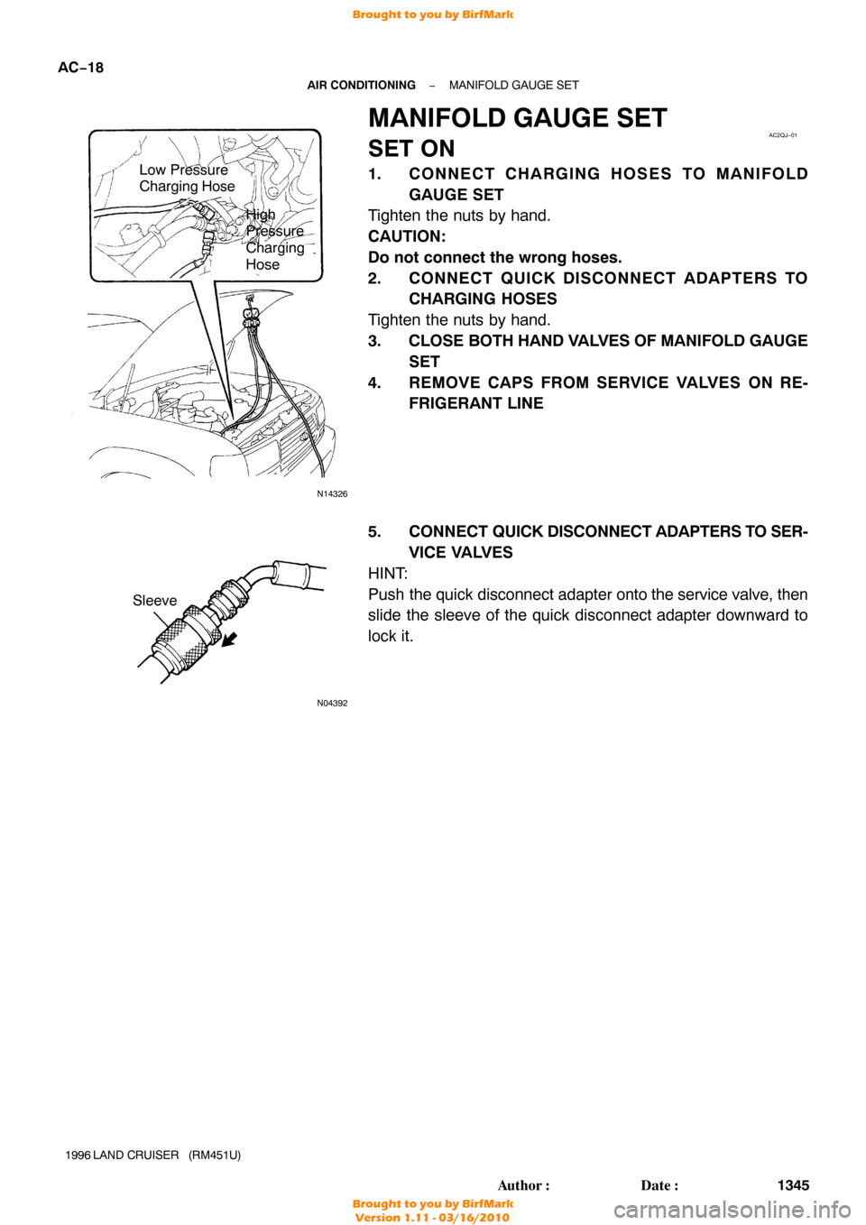
N14326
Low Pressure
Charging Hose
High
Pressure
Charging
Hose
AC2QJ−01
N04392
Sleeve
AC−18
−
AIR CONDITIONING MANIFOLD GAUGE SET
1345
Author�: Date�:
1996 LAND CRUISER (RM451U)
MANIFOLD GAUGE SET
SET ON
1. CONNECT CHARGING HOSES TO MANIFOLD
GAUGE SET
Tighten the nuts by hand.
CAUTION:
Do not connect the wrong hoses.
2. CONNECT QUICK DISCONNECT ADAPTERS TO CHARGING HOSES
Tighten the nuts by hand.
3. CLOSE BOTH HAND VALVES OF MANIFOLD GAUGE
SET
4. REMOVE CAPS FROM SERVICE VALVES ON RE- FRIGERANT LINE
5. CONNECT QUICK DISCONNECT ADAPTERS TO SER-
VICE VALVES
HINT:
Push the quick disconnect adapter onto the service valve, then
slide the sleeve of the quick disconnect adapter downward to
lock it.
Brought to you by BirfMark
Brought to you by BirfMark
Version 1.11 - 03/16/2010
Page 62 of 1399
AC2QK−01
N06553
−
AIR CONDITIONING MANIFOLD GAUGE SET
AC−19
1996 LAND CRUISER (RM451U)
SET OFF
1. CLOSE BOTH HAND VALVES OF MANIFOLD GAUGE
SET
2. DISCONNECT QUICK DISCONNECT ADAPTERS FROM SERVICE VALVES ON REFRIGERANT LINE
HINT:
Slide the sleeve of the quick disconnect adapter upward to un-
lock the adapter and remove it from the service valve.
3. INSTALL CAPS TO SERVICE VALVES ON REFRIGER-
ANT LINE
t
=
QJL
Brought to you by BirfMark
Brought to you by BirfMark
Version 1.11 - 03/16/2010
Page 63 of 1399
AC2QM−01
AC−20
−
AIR CONDITIONING REFRIGERANT LINE
1347
Author�: Date�:
1996 LAND CRUISER (RM451U)
REFRIGERANT LINE
ON−VEHICLE INSPECTION
1. INSPECTION HOSE AND TUBE CONNECTIONS FOR LOOSENESS
2. INSPECT HOSES AND TUBES FOR LEAKAGE
Using a gas leak detector, check for leakage of refrigerant.
Brought to you by BirfMark
Brought to you by BirfMark
Version 1.11 - 03/16/2010
Page 65 of 1399

REPLACEMENT
1. DISCHARGE REFRIGERANT IN REFRIGERATION SYSTEM
2. REPLACE FAULTY TUBE OR HOSE
NOTICE:
Cap the open f")
AC2QN−01
AC−22
−
AIR CONDITIONING REFRIGERANT LINE
1996 LAND CRUISER (RM451U)
REPLACEMENT
1. DISCHARGE REFRIGERANT IN REFRIGERATION SYSTEM
2. REPLACE FAULTY TUBE OR HOSE
NOTICE:
Cap the open fittings immediately to keep moisture or dirt out of the sy\
stem.
3. TORQUE CONNECTIONS TO SPECIFIED TORQUE
NOTICE:
Connections should not be torqued tighter than the specified torque.
Part tightenedN·mkgf·cmft·lbf
Compressor x Discharge hose101007
Compressor x Suction hose101007
Condenser x Discharge hose101007
Condenser x Liquid tube101007
Reciever x Liquid tube5.45548 in.·lbf
Pressure switch x Liquid tube101007
Cooling unit x Liquid tube101007
Expansion valve x Evaporator5.45548 in.·lbf
Cooling unit x Suction tube101007
Liquid tube (Piping joint)1414010
Suction line (Block joint)101007
4. EVACUATE AIR IN REFRIGERATION SYSTEM AND CHARGE WITH REFRIGERANT
Specified amount: 850 ± 50 g (29.98 ± 1.76 oz.)
5. INSPECT FOR LEAKAGE OF REFRIGERANT
Using a gas leak detector, check for leakage of refrigerant.
If there is leakage, check the tightening torque at the joints.
6. INSPECT AIR CONDITIONING OPERATION
Brought to you by BirfMark
Brought to you by BirfMark
Version 1.11 - 03/16/2010
Page 67 of 1399

REMOVAL
1. DISCHARGE REFRIGERANT FROM REFRIGERA TION
SYSTEM
HINT:
At the time of installation, refer to")
AC2QO−03
N06172
N14293
AC−24
−
AIR CONDITIONING COOLING UNIT
1996 LAND CRUISER (RM451U)
REMOVAL
1. DISCHARGE REFRIGERANT FROM REFRIGERA TION
SYSTEM
HINT:
At the time of installation, refer to the following procedure.
�Evacuate air from refrigeration system.
�Charge system with refrigerant and inspect for leakage of
refrigerant.
Specified amount:
850 ± 50 g (29.98 ± 1.76 oz.)
2. DISCONNECT SUCTION TUBE AND LIQUID TUBE
FROM COOLING UNIT FITTING
Remove the 2 bolts and both tubes. Torque: 10 N·m (100 kgf·cm, 7 ft·lbf)
NOTICE:
Cap the open fittings immediately to keep moisture or dirt
out of the system.
HINT:
At the time of indtallation, lubricate 2 new O −rings with com-
pressor oil and install the tubes.
3. REMOVE THESE PARTS:
(a) Glove compratment door (See page BO−76)
(b) Glove compratment door reinforcement (See page BO−76 )
4. REMOVE COOLING UNIT
(a) Disconnect the connectors.
(b) Remove the 4 screws, 2 nuts and cooling unit.
Brought to you by BirfMark
Brought to you by BirfMark
Version 1.11 - 03/16/2010

AUTOMATIC TRANSMISSION SYSTEM
PRECAUTION
If the vehicle is equipped with a mobile communication system,")

3. CHARGE REFRIGERANT INTO REFRIGERANT SYS-
TEM
If there is no leak after refrigerant leak check charge, the proper
a")


SET OFF
1. CLOSE BOTH HAND VALVES OF MANIFOLD GAUGE
SET
2. DISCONNECT QUICK DISCONNECT ADAPTERS FROM SERV")