Page 939 of 1399

CHASSIS
INSPECTION
1. INSPECT STEERING LINKAGE
(a) Check the steering linkage for looseness or damage.")
MA04V−01
P22573
−
MAINTENANCE CHASSIS
MA−7
47
Author�: Date�:
1996 LAND CRUISER (RM451U)
CHASSIS
INSPECTION
1. INSPECT STEERING LINKAGE
(a) Check the steering linkage for looseness or damage.
�Check that the tie rod ends do not have excessive
play.
�Check that the boot clamps are not loose.
(b) Inspect the dust cover for damage.
2. INSPECT SRS AIRBAG (Driver airbag: See page RS−9 )
(Front passenger airbag: See page RS−23 )
3. INSPECT STEERING GEAR HOUSING OIL
Check the steering gear housing for oil leakage.
If leakage is found, check for cause and repair.
4. INSPECT OIL LEVEL IN AUTOMATIC TRANSMISSION
(See page DI−131 )
5. INSPECT OIL LEVEL IN TRANSFER AND DIFFEREN- TIAL
(a) Transfer: Remove the filler plug and feel inside the hole with your
finger. Check that the oil comes to within 5 mm (0.20 in.)
of the bottom edge of the hole.
If the level is low, add oil until it begins to run out of the filler hole.
Oil drade: API GL −4 or GL−5
Viscosity: 75W−90
(b) Differential: Remove the filler plug and feel inside the hole with your
finger. Check that the oil comes to within 5 mm (0.20 in.)
of the bottom edge of the hole.
If the level is low, add oil until it begins to run out of the filler hole.
Oil drade: Hypoid gear oil API GL −5
Viscosity:
Above −18°C (0° F) SAE 90
Below −18°C (0° F) SAE 80W−90 or 80W
6. REPLACE AUTOMATIC TRANSMISSION FLUID (See page DI−3)
Brought to you by BirfMark
Brought to you by BirfMark
Version 1.11 - 03/16/2010
Page 970 of 1399
PP3KT−01
−
PREPARATION AUTOMATIC TRANSMISSION
PP−29
78
Author�: Date�:
1996 LAND CRUISER (RM451U)
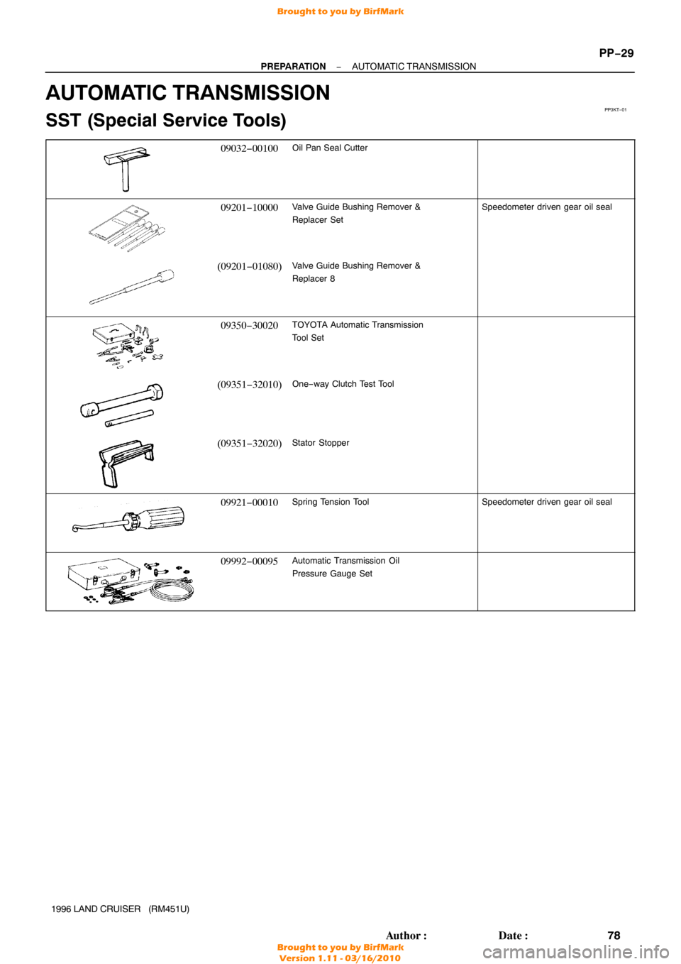
AUTOMATIC TRANSMISSION
SST (Special Service Tools)
09032−00100Oil Pan Seal Cutter
09201−10000Valve Guide Bushing Remover &
Replacer SetSpeedometer driven gear oil seal
(09201−01080)Valve Guide Bushing Remover &
Replacer 8
09350−30020TOYOTA Automatic Transmission
Tool Set
(09351−32010)One−way Clutch Test Tool
(09351−32020)Stator Stopper
09921−00010Spring Tension ToolSpeedometer driven gear oil seal
09992−00095Automatic Transmission Oil
Pressure Gauge Set
Brought to you by BirfMark
Brought to you by BirfMark
Version 1.11 - 03/16/2010
Page 984 of 1399

09504−00011Differential Side Bearing
Adjusting Nut WrenchFront differential
Rear differential
09504−2201")
−
PREPARATION SUSPENSION AND AXLE
PP−43
92
Author�: Date�:
1996 LAND CRUISER (RM451U)
09504−00011Differential Side Bearing
Adjusting Nut WrenchFront differential
Rear differential
09504−22011Differential Side Bearing
ReplacerRear differential
09506−35010Differential Drive Pinion Rear
Bearing ReplacerRear differential
Rear suspension
09509−25011Rear Axle Bearing Lock Nut
WrenchRear axle
09517−36010Rear Axle Shaft Oil Seal
Replacer −Rear axle
09550−10013Replacer Set ”B”Rear differential
Rear suspension
(09553−10010)Differential Side Bearing
Replacer
(09557−10011)Differential Drive Pinion
Front Bearing Replacer
09550−60010Differential Side Bearing
ReplacerRear differential
09556−22010Drive Pinion Front Bearing
RemoverFront differential
Rear differential
09605−60010Steering Knuckle Bearing Cup
Replacer−Front axle
09606−60020Steering Knuckle Bearing RemoverFront axle
09607−60020Front Wheel Adjusting Nut WrenchFront axle
Brought to you by BirfMark
Brought to you by BirfMark
Version 1.11 - 03/16/2010
Page 985 of 1399
PP−44
−
PREPARATION SUSPENSION AND AXLE
93
Author�: Date�:
1996 LAND CRUISER (RM451U)
09611−22012Tie Rod End PullerFront axle
09612−65014Steering Worm Bearing PullerFront axle
(09612−01010)Claw ”A”
(09612−01050)Hanger Pin with Nut
09618−60010Front Axle & Drive Shaft Bearing
ReplacerFront axle
09710−22021Front Suspension Bushing Tool
SetRear suspension
(09710−01071)Lower Arm Bushing Remover
09710−22042Rear Suspension Bushing Tool SetFront suspension
(09710−02051)Base
(09710−02061)Replacer
(09710−02071)Bushing Remover & Replacer
09710−30050Suspension Arm Bushing ReplacerFront suspension
09726−40010Lower Control Shaft Bearing
ReplacerFront differential
Rear differential
Brought to you by BirfMark
Brought to you by BirfMark
Version 1.11 - 03/16/2010
Page 1064 of 1399

TROUBLESHOOTING
PROBLEM SYMPTOMS TABLE
Use the table below to help you find the cause of the")
SA1U7−01
−
SUSPENSION AND AXLE TROUBLESHOOTING
SA−1
858
Author�: Date�:
1996 LAND CRUISER (RM451U)
TROUBLESHOOTING
PROBLEM SYMPTOMS TABLE
Use the table below to help you find the cause of the problem. The numbers \
indicate the priority of the likely
cause of the problem. Check each part in order. If necessary, replace these parts.
(w/ Differential locking system):
�Check that center differential lock mode is set.
�When switching differential Free↔Lock, the indicator lamp will blink if the gears of the differen-
tial lock sleeve are not meshed. If this occurs, when the tires are rotated \
to apply differential
power to the differential, the differential locks and the indicator lamp\
light up.
SymptomSuspect AreaSee page
Wander/ pulls
1. Tires: worn or improperly inflated
2. Wheel alignmemt: incorrect
3. Steering linkage: loosen or worn
4. Hub bearings: loosen or worn
5. Steering gear: out of adjustment or brokenSA−3
SA−4
SR−47 SA−8
SR−41
Bottoming
1. Vehicle: overloaded
2. Spring weak
3. Shock absorber: worn out−
SA−49
SA−49
Sways/ pitches
1. Tires: worn or improperly inflated
2. Stabilizer bar: bent or broken
3. Shock absorber: worn outSA−3
SA−60
SA−49
Front wheel shimmy
1. Tires: worn or improperly inflated
2. Wheels: out of balance
3. Shock absorber: worn out
4. Wheel alignmemt: incorrect
5. Hub bearings: loosen or worn
6. Steering linkage: loosen or worn
7. Steering gear: out of adjustment or brokenSA−3
SA−3
SA−49 SA−3
SA−7
SR−45
SR−38
Abnormal tire wear
1. Tires: worn or improperly inflated
2. Wheel alignmemt: incorrect
3. Suspension parts: worn out
4. Shock absorber: worn outSA−3
SA−3 −
SA−49
Noise in front dif ferential
1. Oil level: low or wrong grade
2. Excessive backlash between pinion and ring gear
3. Ring, pinion ro side gears: worn or chipped
4. Pinion shaft bearing: worn
5. Side bearing: worn
6. Differential bearing: loosen or wornSA−21
SA−29
SA−29
SA−29
SA−29
SA−29
Oil leak from front dif ferential
1. Oil level: too high or wrong grade
2. Drive pinion oil seal: worn or damaged
3. Side gear oil seal: worn or damaged
4. Companion flange: loosen or damaged
5. Side gear shaft: damagedSA−21
SA−29
SA−29
SA−29
SA−29
Noise in rear axle
1. Oil level: low or wrong grade
2. Excessive backlash between pinion and ring gear
3. Ring, pinion ro side gears: worn or chipped
4. Pinion shaft bearing: worn
5. Axle shaft bearing: worn
6. Differential bearing: loosen or wornSA−73
SA−87
SA−87
SA−87
SA−87
SA−87
Oil leak from rear axle1. Oil seal: worn or damaged
2. Rear axle housing: crackedSA−73
−
Brought to you by BirfMark
Brought to you by BirfMark
Version 1.11 - 03/16/2010
Page 1103 of 1399

(c) Adjust the drive pinion preload by tightening the compan-
ion fla")
SA2401
SST
SA2403
SA2161
MP Grease
Z10100
SA−40
−
SUSPENSION AND AXLE FRONT DIFFERENTIAL CARRIER
1996 LAND CRUISER (RM451U)
(c) Adjust the drive pinion preload by tightening the compan-
ion flange nut.
Using SST to hold the flange, tighten the nut.
SST 09330−00021
NOTICE:
As there is no spacer, tighten a little at a time, being careful
not to overtighten.
(d) Using a torque wrench, measure the preload. Preload (at starting):
New bearing
0.9 − 1.6 N·m (10 − 16 kgf·cm, 8.7 − 13.9 in.·lbf)
Reused bearing
0.5 − 0.8 N·m (5 − 8 kgf·cm, 4.3 − 6.9 in.·lbf)
HINT:
Measure the total preload after first turning the bearing clock-
wise and counterclockwise several times to mark the bearing
smooth.
12. w/o DIFFERENTIAL LOCK: INSTALL DIFFERENTIAL CASE IN CARRIER
(a) Place the bearing outer races on their respective bear- ings. Make sure the left and right outer races are not inter-
changed.
(b) Install the case in the carrier.
HINT:
Make sure that there is backlash between the ring gear and
drive pinion.
13. w/ DIFFERENTIAL LOCK: INSTALL DIFFERENTIAL CASE IN CARRIER
(a) Apply MP grease on the rack of the shift fork and connect- ing part of the indicator switch.
(b) Insert the shift fork into the differential carrier, as shown.
(c) Install outer races, adjusting nuts and left side to sleeve.
HINT:
Check that the sleeve moves smoothly.
(d) Install the shift fork in the groove of the sleeve holding it by hand and install the case in the carrier.
HINT:
Make sure that there is backlash between the ring gear and
drive pinion.
Brought to you by BirfMark
Brought to you by BirfMark
Version 1.11 - 03/16/2010
Page 1144 of 1399

5. CHECK SIDE GEAR BACKLASH
Using a dial indicator, measure the side gear backlash with")
SA2131
SA2134
SA2448
SST
−
SUSPENSION AND AXLE REAR DIFFERENTIAL CARRIER
SA−81
1996 LAND CRUISER (RM451U)
5. CHECK SIDE GEAR BACKLASH
Using a dial indicator, measure the side gear backlash with
holding one pinion gear toward the case.
Backlash: 0.02 − 0.20 mm (0.0008 − 0.0079 in.)
If the backlash is not within the specification, install the correct
thrust washers (See page SA−87).
6. CHECK TOOTH CONTACT BETWEEN RING GEAR
AND DRIVE PINION (See page SA−35 )
7. w/ DIFFERENTIAL LOCK: REMOVE INDICATOR SWITCH
Remove the indicator switch and gasket.
8. w/ DIFFERENTIAL LOCK: REMOVE COVER
(a) Remove the 3 bolts.
(b) Using a brass bar and hammer, tap on the cover to re- move it.
9. w/ DIFFERENTIAL LOCK: REMOVE SLEEVE
(a) Remove the 4 bolts.
(b) Using a plastic hammer, tap the actuator.
(c) Remove the actuator and sleeve.
10. w/ DIFFERENTIAL LOCK: REMOVE ACTUATOR AND SHIFT FORK AND SHAFT
(a) Remove the shift fork shaft bolt.
(b) Pull out the actuator and remove the shift fork.
11. REMOVE COMPANION FLANGE
(a) Using a chisel and hammer, unstick the nut.
(b) Using SST to hold the flange, remove the nut and plate washer.
SST 09330−00021
Brought to you by BirfMark
Brought to you by BirfMark
Version 1.11 - 03/16/2010
Page 1154 of 1399

(d) Adjust the drive pinion preload by tightening the compan-
ion flange nut.
Usi")
SA2450
SST
SA2446
R08261
R08262
−
SUSPENSION AND AXLE REAR DIFFERENTIAL CARRIER
SA−91
1996 LAND CRUISER (RM451U)
(d) Adjust the drive pinion preload by tightening the compan-
ion flange nut.
Using SST to hold the flange, tighten the nut.
SST 09330−00021
NOTICE:
Coat the nut and screw of the drive pinion with gear oil. As
there is no spacer, tighten a little at a time, being careful not
to overtighten.
(e) Using a torque wrench, measure the preload. Preload (at starting):
New bearing
1.3 − 2.0 N·m (13 − 20 kgf·cm, 11.3 − 17.4 in.·lbf)
Reused bearing
0.7 − 1.0 N·m (7 − 10 kgf·cm, 6.1 − 8.7 in.·lbf)
HINT:
Measure the total preload after first turning the bearing clock-
wise and counterclockwise several times to make the bearing
smooth.
10. w/o DIFFERENTIAL LOCK: INSTALL DIFFERENTIAL CASE IN CARRIER
(a) Place the 2 bearing outer races on their respective bear- ings. Make sure that the left and right outer races are not
interchanged.
(b) Install the case in the carrier.
HINT:
Make sure that there is backlash between the ring gear and
drive pinion.
11. w/ DIFFERENTIAL LOCK: INSTALL DIFFERENTIAL CASE IN CARRIER
(a) Place the 2 bearing outer races on their respective bear- ings. Make sure that the left and right races are not inter-
changed.
(b) Install the assembled plate washer onto the side bearing.
(c) Install the differential case in the carrier.
(d) Make the plate washer and bearing smooth by tapping on
the ring gear with a plastic hammer.
HINT:
If it is difficult to install the differential case into the carrier, re-
place the plate washer with a thinner one.
However, select a plate washer that allows no clearance be-
tween it and the carrier.
Brought to you by BirfMark
Brought to you by BirfMark
Version 1.11 - 03/16/2010