Page 789 of 1399

EM1Q4−01
P05120A16078
1 Dot Mark
EM−4
−
ENGINE MECHANICAL VALVE CLEARANCE
507
Author�: Date�:
1996 LAND CRUISER (RM451U)
VALVE CLEARANCE
INSPECTION
HINT:
Inspect and adjust the valve clearance when the engine is cold.
1. DRAIN ENGINE COOLANT
2. REMOVE THROTTLE BODY (See page SF−45)
3. DISCONNECT ENGINE WIRE AND HEATER VALVE FROM COWL PANEL
(a) Remove the 2 bolts and disc onnect the ground strap and
engine wire.
(b) Remove the 2 bolts and disconnect the heater valve.
4. DISCONNECT HIGH −TENSION CORDS FROM SPARK
PLUGS (See page IG−1 )
5. REMOVE CYLINDER HEAD COVER
Remove the 13 bolts, cylinder head cover and gasket.
6. SET NO. 1 CYLINDER TO TDC/COMPRESSION
(a) Turn the crankshaft pulley, and align its groove with the timing mark ”0” of the timing chain cover.
(b) Check that the timing marks (1 and 2 dots) of the camshaft
drive and driven gears are in straight line on the cylinder
head surface as shown in the illustration.If not, turn the
crankshaft 1 revolution (360 °) and align the marks as
above.
Brought to you by BirfMark
Brought to you by BirfMark
Version 1.11 - 03/16/2010
Page 792 of 1399

EM0494
−
ENGINE MECHANICAL VALVE CLEARANCE
EM−7
510
Author�: Date�:
1996 LAND CRUISER (RM451U)
9. Rear valves of No. 6 cylinder
ADJUST VALVE CLEARANCE
(a) Remove the distributor (See page IG−10).
(b) Remove the camshafts (See page EM−28).
(c) Remove the adjusting shim with a small screwdriver.
(d) Determine the replacement adjusting shim size by follow- ing the Formula or Charts:
�Using a micrometer, measure the thickness of the
removed shim.
�Calculate the thickness of a new shim so that the
valve clearance comes within specified value.
T ....... Thickness of removed shim
A ....... Measured valve clearance
N ....... Thickness of new shim
Intake: N = T + (A − 0.20 mm (0.008 in.))
Exhaust: N = T + (A − 0.30 mm (0.012 in.))
�Select a new shim with a thickness as close as pos-
sible to the calculated value.
HINT:
Shims are available in 17 sized in increments of 0.05 mm
(0.0020 in.), from 2.50 mm (0.0984 in.) to 3.30 mm (0.1299 in.).
(e) Place a new adjusting shim on the valve lifters.
(f) Install the camshafts (See page EM−54 ).
(g) Recheck the valve clearance.
(h) Install the distributor (See page IG−11 ).
10. REINSTALL CYLINDER HEAD COVER
(a) Install the gasket to the cylinder head cover.
(b) Install the cylinder head cover with the 13 bolts.
11. RECONNECT HIGH −TENSION CORDS TO SPARK
PLUGS (See page IG−1 )
12. RECONNECT HEA TER VALVE AND ENGINE WIRE TO
COWL PANEL
(a) Connect the heater valve with the 2 bolts.
(b) Connect the ground strap and engine wire with the 2 bolts.
13. REINSTALL THROTTLE BODY (See page SF−48 )
14. REFILL RADIATOR WITH ENGINE COOLANT
15. CHECK AND ADJUST IGNITION TIMING (See page EM−10 )
Brought to you by BirfMark
Brought to you by BirfMark
Version 1.11 - 03/16/2010
Page 798 of 1399
EM1E9−01
−
ENGINE MECHANICAL TIMING CHAIN
EM−13
1996 LAND CRUISER (RM451U)
REMOVAL
1. DRAIN ENGINE OIL
2. DRAIN ENGINE COOLANT
3. REMOVE ENGINE UNDER COVER
4. REMOVE RADIATOR (See page CO−14 )
5. DISCONNECT A/C COMPRESSOR AND BRACKET
(a) Loosen the idler pulley nut and adjusting bolt, and remove
the drive belt.
(b) Remove the 4 mounting bolts, and disconnect the com- pressor from the bracket.
HINT:
Put aside the compressor, and suspend it.
(c) Remove the 5 bolts and A/C compressor bracket.
6. REMOVE RADIATOR PIPE
(a) Disconnect the No. 2 radiator hose from the water inlet.
(b) Remove the 2 nuts and radiator pipe.
7. REMOVE WATER PUMP
Remove the 4 bolts, 2 nuts, water pump and gasket.
8. REMOVE CYLINDER HEAD (See page EM−28 )
Brought to you by BirfMark
Brought to you by BirfMark
Version 1.11 - 03/16/2010
Page 800 of 1399

−
ENGINE MECHANICAL TIMING CHAIN
EM−15
1996 LAND CRUISER (RM451U)
15. CHECK THRUST CLEARANCE OF OIL PUMP DRIVE
SHAFT GEAR
Using a dial indicator with lever type attachment, measure the
thrust clearance.
Standard thrust clearance:
0.040 − 0.160 mm (0.0016 − 0.0063 in.)
Maximum thrust clearance: 0.30 mm (0.0118 in.)
If the thrust clearance is greater than maximum, replace the oil
pump drive shaft gear and/or timing chain cover.
16. REMOVE DRIVE BELT IDLER PULLEY
Remove the bolt and idler pulley.
17. REMOVE TIMING CHAIN COVER
(a) Remove the 9 mounting bolts, 2 mounting nuts and drive belt adjusting bar.
(b) Remove the oil pump by prying the portions between the cylinder block and oil pump with a screwdriver.
NOTICE:
Be careful not to damage the contact surfaces of the cylin-
der block and oil pump.
(c) Remove the O−rings from the oil pump.
(d) Remove the gasket from the oil pump.
18. REMOVE TIMING CHAIN AND CAMSHAFT TIMING GEAR
Brought to you by BirfMark
Brought to you by BirfMark
Version 1.11 - 03/16/2010
Page 808 of 1399

−
ENGINE MECHANICAL TIMING CHAIN
EM−23
1996 LAND CRUISER (RM451U)
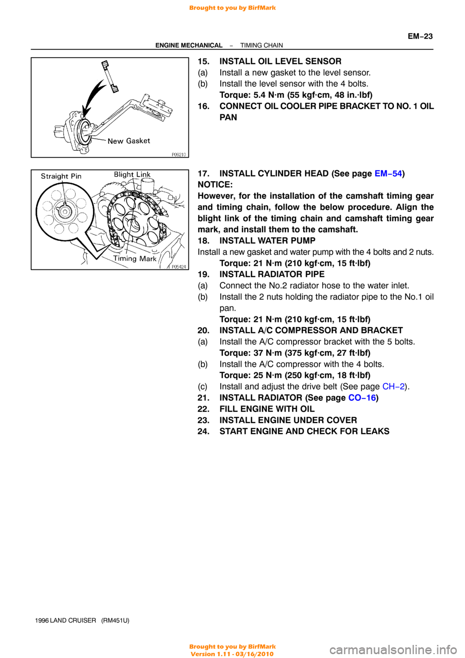
15. INSTALL OIL LEVEL SENSOR
(a) Install a new gasket to the level sensor.
(b) Install the level sensor with the 4 bolts.
Torque: 5.4 N·m (55 kgf·cm, 48 in.·lbf)
16. CONNECT OIL COOLER PIPE BRACKET TO NO. 1 OIL
PA N
17. INSTALL CYLINDER HEAD (See page EM−54 )
NOTICE:
However, for the installation of the camshaft timing gear
and timing chain, follow the below procedure. Align the
blight link of the timing chain and camshaft timing gear
mark, and install them to the camshaft.
18. INSTALL WATER PUMP
Install a new gasket and water pump with the 4 bolts and 2 nuts.
Torque: 21 N·m (210 kgf·cm, 15 ft·lbf)
19. INSTALL RADIATOR PIPE
(a) Connect the No.2 radiator hose to the water inlet.
(b) Install the 2 nuts holding the radiator pipe to the No.1 oil
pan.
Torque: 21 N·m (210 kgf·cm, 15 ft·lbf)
20. INSTALL A/C COMPRESSOR AND BRACKET
(a) Install the A/C compressor bracket with the 5 bolts.
Torque: 37 N·m (375 kgf·cm, 27 ft·lbf)
(b) Install the A/C compressor with the 4 bolts. Torque: 25 N·m (250 kgf·cm, 18 ft·lbf)
(c) Install and adjust the drive belt (See page CH−2).
21. INSTALL RADIATOR (See page CO−16 )
22. FILL ENGINE WITH OIL
23. INSTALL ENGINE UNDER COVER
24. START ENGINE AND CHECK FOR LEAKS
Brought to you by BirfMark
Brought to you by BirfMark
Version 1.11 - 03/16/2010
Page 817 of 1399
P08374A16075
1 Dot Mark
EM−32
−
ENGINE MECHANICAL CYLINDER HEAD
1996 LAND CRUISER (RM451U)
30. REMOVE CYLINDER HEAD COVER
Remove the 13 bolts, cylinder head cover and gasket.
31. REMOVE SPARK PLUGS
32. SET NO. 1 CYLINDER TO TDC/COMPRESSION
(a) Turn the crankshaft pulley and align its groove with the ”0”
mark on the timing chain cover.
(b) Check that the timing marks (1 and 2 dots) of the camshaft
drive and driven gears are in straight line on the cylinder
head surface as shown in the illustration.
If not, turn the crankshaft 1 revolution (360° ) and align the
marks as above.
33. REMOVE CHAIN TENSIONER
Remove the 2 nuts, chain tensioner and gasket.
34. REMOVE CAMSHAFT TIMING GEAR
(a) Remove the semi−circular plug.
(b) Place the matchmarks on the camshaft timing gear and timing chain.
(c) Hold the intake camshaft with a wrench, remove the bolt and distributor gear.
Brought to you by BirfMark
Brought to you by BirfMark
Version 1.11 - 03/16/2010
Page 844 of 1399

Front Mark
P09890
Push
P08374A16075
1 Dot Mark
−
ENGINE MECHANICAL CYLINDER HEAD
EM−59
1996 LAND CRUISER (RM451U)
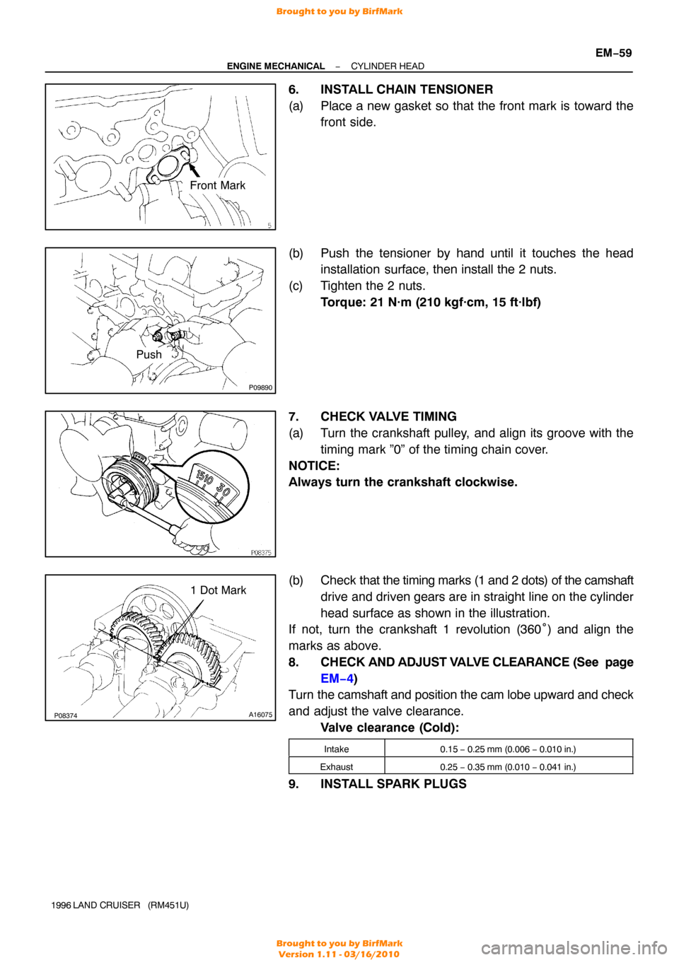
6. INSTALL CHAIN TENSIONER
(a) Place a new gasket so that the front mark is toward the
front side.
(b) Push the tensioner by hand until it touches the head installation surface, then install the 2 nuts.
(c) Tighten the 2 nuts. Torque: 21 N·m (210 kgf·cm, 15 ft·lbf)
7. CHECK VALVE TIMING
(a) Turn the crankshaft pulley, and align its groove with the timing mark ”0” of the timing chain cover.
NOTICE:
Always turn the crankshaft clockwise.
(b) Check that the timing marks (1 and 2 dots) of the camshaft
drive and driven gears are in straight line on the cylinder
head surface as shown in the illustration.
If not, turn the crankshaft 1 revolution (360° ) and align the
marks as above.
8. CHECK AND ADJUST VALVE CLEARANCE (See page
EM−4)
Turn the camshaft and position the cam lobe upward and check
and adjust the valve clearance.
Valve clearance (Cold):
Intake0.15 − 0.25 mm (0.006 − 0.010 in.)
Exhaust0.25 − 0.35 mm (0.010 − 0.041 in.)
9. INSTALL SPARK PLUGS
Brought to you by BirfMark
Brought to you by BirfMark
Version 1.11 - 03/16/2010
Page 885 of 1399

P04907
P08469
SST
EM−100
−
ENGINE MECHANICAL CYLINDER BLOCK
1996 LAND CRUISER (RM451U)
2. REPLACE OVERSIZED (O/S) PISTONS FOR CYLIN-
DER BORING
HINT:
�Bore all the 6 cylinders for the O/S piston outside diame-
ter.
�Replace all the piston rings with ones to match the O/S
pistons.
(a) Keep 6 new O/S pistons. O/S piston diameter:
O/S 0.50100.450 − 100.480 mm (3.9547 − 3.9559 in.)
O/S 1.00100.950 − 100.980 mm (3.9744 − 3.9756 in.)
(b) Using a micrometer, measure the piston diameter at right
angles to the piston pin center line, 42 mm (1.65 in.) from
the piston head.
(c) Calculate the amount of each cylinder is to be rebored as
follows:
Size to be rebored = P + C − H
P = Piston diameter
C = Piston oil clearance
0.040 − 0.060 mm (0.0016 − 0.0024 in.)
H = Allowance for honing
0.02 mm (0.0008 in.) or less
(d) Bore and hone the cylinders to calculated dimensions. Maximum honing: 0.02 mm (0.0008 in.)
NOTICE:
Excess honing will destroy the finished roundness.
3. REPLACE CRANKSHAFT FRONT OIL SEAL
HINT:
There are 2 methods ((a) and (b)) to replace the oil seal.
(a) If the timing chain cover is removed from the cylinder block:
(1) Using a screwdriver and a hammer, tap out the oilseal.
(2) Using SST and a hammer, tap in a new oil seal until
its surface is flush with the timing chain cover edge.
SST 09316−60011 (09316 −00011, 09316−00051)
(3) Apply MP grease to the oil seal lip.
NOTICE:
Do not let foreign matter get onto the lip of the oil seal.
Brought to you by BirfMark
Brought to you by BirfMark
Version 1.11 - 03/16/2010