Page 606 of 1399

Q08577D00180
ECM
Combination Meter
Battery
Park/Neutral
Position Switch
Fuse Block
Starter
From
Battery L
2
R
NSW
E717
16 15
C12
G−W
E7E7
E7
L
R
2
C12
C12
R−B R−B
G−W
O
O
IH2
B−W 22
43
1
2B−W
IG1
ST1 2 4
AM1
2
2
2 2
1
2
AM1
3
J4
EA2 1 8
GAUGE
W
B F6
FLAM1
B+
IH2
IH1 IH1
B−L
B
6
Ignition Switch
4 R/B No. 2
6
6
B
B
Y
Y
15
B−R
B−WO
G−R R−B
S1
S2
10 4
11
2
3
21 7
Y
B−Y 1
−
DIAGNOSTICS AUTOMATIC TRANSMISSION
DI−169
1996 LAND CRUISER (RM451U)
DTC P1780 Park/Neutral Position Switch Malfunction
CIRCUIT DESCRIPTION
The park/neutral position switch detects the shift lever position and sends\
signals to the ECM.
The ECM receives signals (NSW, R, 2 and L) from the park/neutral position switch. When the signal is\
not
sent to the ECM from the park/neutral position switch, the ECM judges th\
at the shift lever is in D position.
DTC No.DTC Detection ConditionTrouble Area
P1780
2 or more switches are ON simultaneously for N, 2 and L posi-
tions (2 trip detection logic)
�Short in park/neutral position switch circuit
� Park/neutral position switch
� ECMWhen driving under conditions (a), (b) and (c) for 30 sec. or
more, the park/neutral position switch is ON (N position)
(2 trip detection logic)
(a) Vehicle speed: 70 km/h (44 mph) or more
(b) Engine speed: 1,500 − 2,500 rpm
(c) Engine load: 0.6 g/rev. or more
WIRING DIAGRAM
DI5KY−02
Brought to you by BirfMark
Brought to you by BirfMark
Version 1.11 - 03/16/2010
Page 611 of 1399
Q08582
ECM
O/D OFF Indicator Light
(Combination Meter)
Ignition Switch
Fuse BlockO/D Main Switch* E7
2
P−L
B−L Y
GAUGE
Battery B+
W
2
Y
3 2
4 4
2
2 2
4
W−B
6
FL AM1
B−Y
22
E6 A
A
EA2 C12
C12
19
OD2
B ID2
J1
B 9
1
1 8
3
Fuse Block
P−L
P−L
AM1
2
BF
R/B No. 2 R/B No. 2
O/D Main switch
Contact go off with switch pushed in.
Contact go on with switch once again.
*:
DI−174
−
DIAGNOSTICS AUTOMATIC TRANSMISSION
1996 LAND CRUISER (RM451U)
O/D Main Switch & O/D OFF Indicator Light Circuit
CIRCUIT DESCRIPTION
The O/D main switch contacts go off when the switch is pushed in and come on when it is pushed once again.\
In O/D main switch OFF position, the O/D OFF indicator lights up, and the \
ECM prohibits shifting to O/D.
WIRING DIAGRAM
DI5L3−03
Brought to you by BirfMark
Brought to you by BirfMark
Version 1.11 - 03/16/2010
Page 619 of 1399

Q08580
R−W
J1
A
W 5BRY
IG3
O
Ignition Switch
Fuse Block
GAUGE
Pattern Select Switch*
(2nd Start Switch)
B ECM
18
IH2 12
HI
1
113
9
E4
2C12
Battery
FL AM1
Fuse Block
B−L
W
B−Y
2
4
F6
6 A
A
Y
3
1
E4HOLD
2
EA2
AM1
22
1
AM1 IG1
B
C12
ID3 IH2
O
R−W
2 2
3
42nd STRT Indicator Light
(Combination Meter)
12
Y
R/B No. 2 R/B No. 2
Pattern Select Switch (2nd Start Switch)
When the 2nd start switch is pushed, the switch is contacted and the 2nd\
mode is selected.
To cancel the 2nd start, push the 2nd start swtch once again. The 2nd star\
t is automatically cancelled
out when the ignition switch is turned OFF.
*:
DI−182
−
DIAGNOSTICS AUTOMATIC TRANSMISSION
1996 LAND CRUISER (RM451U)
Pattern Select Switch Circuit (2nd Start Switch) & 2nd Start
Switch Indicator Light Circuit
CIRCUIT DESCRIPTION
When 2nd start mode is selected with the pattern select switch, the ECM cont\
rols the solenoid valves and
the transmission starts from 2nd gear.
In D position, the transmission automatically shifts up through 3rd to O\
/D as usual.
In 2nd position, the transmission is held in 2nd gear.
WIRING DIAGRAM
DI5L8−03
Brought to you by BirfMark
Brought to you by BirfMark
Version 1.11 - 03/16/2010
Page 622 of 1399

Q08580
R-W
J1
A
W 5BRY
IG3
O
Ignition Switch
Fuse Block
GAUGE
(*) Pattern Select Switch
(2nd Start Switch)
B
ECM
18
IH2 12
HI
1
113
9
E4
2
C12
Battery
FL AM1
Fuse Block
B-L
W
B-Y
2
4
F6
6 A
A
Y
3
1
E4HOLD
2
EA2
AM1
22
1
AM1 IG1
B
C12
IG3 IL2
O
R-W
2 2
3
42nd STRT Indicator Light
(Combination Meter)
12
Y
R/B No.2 R/B No.2
DI-185
-
DIAGNOSTICS AUTOMATIC TRANSMISSION
1996 LAND CRUISER (RM451U)
Pattern Select Switch Circuit (2nd Start Switch) & 2nd Start
Switch Indicator Light Circuit
CIRCUIT DESCRIPTION
When 2nd start mode is selected with the pattern select switch, the ECM cont\
rols the solenoid valves and
the transmission starts from 2nd gear.
In D position, the transmission automatically shifts up through 3rd to O\
/D as usual.
In 2nd position, the transmission is held in 2nd gear.
WIRING DIAGRAM
(*) Pattern Select Switch (2nd Start Switch)
When the 2nd start switch is pushed, the switch is contacted and the 2nd\
mode is selected.
To cancel the 2nd start, push the 2nd start switch once again. The 2nd sta\
rt is automatically cancelled out
when the ignition switch is turned OFF.
DI5L8-02
Brought to you by BirfMark
Brought to you by BirfMark
Version 1.11 - 03/16/2010
Page 654 of 1399
W02197
Ignition
Switch
Battery
AM1
F61
B−L 2 2
3
4
W
2 12
AM1R/B No. 2
2
BB
EA2
6
B−Y
42
GAUGEY A
A
J1
Junction
Connector
CENTER DIFF. LOCK
Indicator Light Y
C10
P−B
P−B
P−B
C11
5
A1319
EXI
CENTER
DIFF. LOCK
DETECTION
Switch ABS ECU
2
1
3
R/B No. 2
−
DIAGNOSTICS ANTI−LOCK BRAKE SYSTEM
DI−221
1996 LAND CRUISER (RM451U)
DTC 48 Center Differential Lock Circuit
CIRCUIT DESCRIPTION
DTC No.DTC Detecting ConditionTrouble Area
48Open or short circuit in center differential lock circuit
Center differential is locking�Center differential lock
� Center differential lock circuit
WIRING DIAGRAM
INSPECTION PROCEDURE
1 Check the center differential is free (Transfer is in H position).
NG Repair the center differential lock system.
OK
DI5M9−02
Brought to you by BirfMark
Brought to you by BirfMark
Version 1.11 - 03/16/2010
Page 663 of 1399
W02199
BatteryJunction
Connector
ID
W−B
B−W
ABS Control Relay
1 4
2
6 3
1
4
Motor
Relay
Solenoid
Relay
ABS ECU
ABS ECU
ABS Actuator 4
5
A7
A6
A6 A6
A4 R−L
R−L
DLC1
Short Pin
B−W
IH1
A12
ABS ECU
W
13
C10
GAUGE
2223 ABS
Warning
Light
A
A
J1
C10IH1
20
A7
A7A7
A7
EA3
EA3
2
1 B−W
B−W
B−L OO
O
Y
54
3
23 OY
DI−230
−
DIAGNOSTICS ANTI−LOCK BRAKE SYSTEM
1996 LAND CRUISER (RM451U)
ABS Warning Light Circuit
CIRCUIT DESCRIPTION
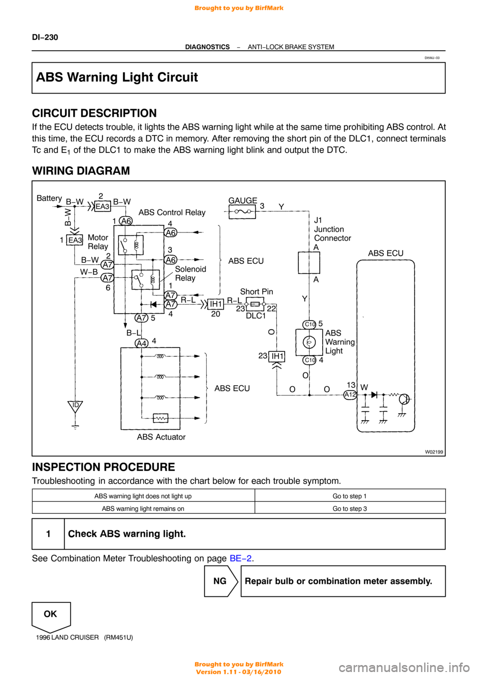
If the ECU detects trouble, it lights the ABS warning light while at the same time prohibiting ABS control. At
this time, the ECU records a DTC in memory. After removing the short pin of the DLC1, connect terminals
Tc and E
1 of the DLC1 to make the ABS warning light blink and output the DTC.
WIRING DIAGRAM
INSPECTION PROCEDURE
Troubleshooting in accordance with the chart below for each trouble symptom.
ABS warning light does not light upGo to step 1
ABS warning light remains onGo to step 3
1 Check ABS warning light.
See Combination Meter Troubleshooting on page BE−2.
NG Repair bulb or combination meter assembly.
OK
DI5MJ−03
Brought to you by BirfMark
Brought to you by BirfMark
Version 1.11 - 03/16/2010
Page 726 of 1399
DI5O8−02
I00756
DLC1
Cruise Control Actuator
� Actuator Motor
� Actuator Magnetic Clutch
� Actuator Position Sensor
Cruise Control ECU
Cruise Control Switch
� Main Switch
� Control Switch
Stop Light Switch
No.1 V ehicle Speed Sensor
Park/Neutral Position Switch
Instrument Panel Fuse Block
�
GAUGE Fuse
� ECU−IG Fuse
� ECU− B Fuse
DI−292
−
DIAGNOSTICS CRUISE CONTROL SYSTEM
1996 LAND CRUISER (RM451U)
PARTS LOCATION
Brought to you by BirfMark
Brought to you by BirfMark
Version 1.11 - 03/16/2010
Page 741 of 1399
I00491
Cruise Control ECU
C17
Speedometer
(Combination Meter)
C13
C13
4 3
Vehicle Speed Sensor (Combination Meter) R−O
R−O
R−G
R−G 25
1
Ea1EC1
IH1L−W
BR Air Intake Chamber
EC
V1
V1
V13 2
1
1
Ea1 EC1
3 6
Y
Y GAUGE
AM1
Y
Y
BR
BR
EC1
Ea1 IH1
22
Instrument Panel Fuse
Block
Fusible Link BatteryWB
B
I12
I12
Ignition Switch 2
4
1
3
F11
F11Y
B
B
J4
JUNCTION
CONNECTOR
EA1
6
2
2 3
4
B−L
FL MAIN
F6
1 B−Y
39
20
SPD
−
DIAGNOSTICS CRUISE CONTROL SYSTEM
DI−307
1996 LAND CRUISER (RM451U)
WIRING DIAGRAM
Brought to you by BirfMark
Brought to you by BirfMark
Version 1.11 - 03/16/2010


