Page 61 of 1399
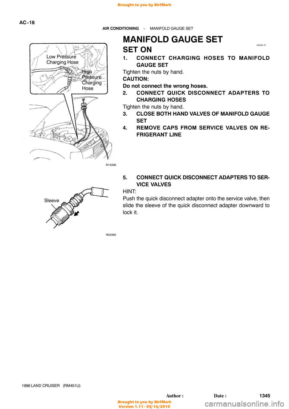
N14326
Low Pressure
Charging Hose
High
Pressure
Charging
Hose
AC2QJ−01
N04392
Sleeve
AC−18
−
AIR CONDITIONING MANIFOLD GAUGE SET
1345
Author�: Date�:
1996 LAND CRUISER (RM451U)
MANIFOLD GAUGE SET
SET ON
1. CONNECT CHARGING HOSES TO MANIFOLD
GAUGE SET
Tighten the nuts by hand.
CAUTION:
Do not connect the wrong hoses.
2. CONNECT QUICK DISCONNECT ADAPTERS TO CHARGING HOSES
Tighten the nuts by hand.
3. CLOSE BOTH HAND VALVES OF MANIFOLD GAUGE
SET
4. REMOVE CAPS FROM SERVICE VALVES ON RE- FRIGERANT LINE
5. CONNECT QUICK DISCONNECT ADAPTERS TO SER-
VICE VALVES
HINT:
Push the quick disconnect adapter onto the service valve, then
slide the sleeve of the quick disconnect adapter downward to
lock it.
Brought to you by BirfMark
Brought to you by BirfMark
Version 1.11 - 03/16/2010
Page 62 of 1399
AC2QK−01
N06553
−
AIR CONDITIONING MANIFOLD GAUGE SET
AC−19
1996 LAND CRUISER (RM451U)
SET OFF
1. CLOSE BOTH HAND VALVES OF MANIFOLD GAUGE
SET
2. DISCONNECT QUICK DISCONNECT ADAPTERS FROM SERVICE VALVES ON REFRIGERANT LINE
HINT:
Slide the sleeve of the quick disconnect adapter upward to un-
lock the adapter and remove it from the service valve.
3. INSTALL CAPS TO SERVICE VALVES ON REFRIGER-
ANT LINE
t
=
QJL
Brought to you by BirfMark
Brought to you by BirfMark
Version 1.11 - 03/16/2010
Page 76 of 1399

AC2R5−01
N06158
−
AIR CONDITIONING COMPRESSOR AND MAGNETIC CLUTCH
AC−33
1360
Author�: Date�:
1996 LAND CRUISER (RM451U)
COMPRESSOR AND MAGNETIC
CLUTCH
ON−VEHICLE INSPECTION
1. INSTALL MANIFOLD GAUGE SET (See page AC−18 )
2. START ENGINE
Run the engine at 1,500 rpm.
3. INSPECT COMPRESSOR FOR METALLIC SOUND
Check if there is a metallic sound from the compressor when the
A/C switch is on.
If metallic sound is heard, replace the compressor assembly.
4. INSPECT REFRIGERANT PRESSURE (See page AC−5 )
5. STOP ENGINE
6. INSPECT VISUALLY FOR LEAKAGE OF REFRIGER- ANT FROM SAFETY SEAL
Using a gas leak detector, check for leakage of refrigerant.
If there is any leakage, replace the compressor assembly.
7. REMOVE MANIFOLD GAUGE SET (See page
AC−19 )
8. MAKE THESE VISUAL CHECKS:
(a) Leakage of grease from the clutch bearing.
(b) Signs of oil on the pressure plate or rotor. Repair or replace, as necessary.
9. INSPECT MAGNETIC CLUTCH BEARING FOR NOISE
(a) Start engine.
(b) Check for abnormal noise from near the compressor when the A/C switch is OFF.
If abnormal noise is being emitted, replace the magnetic clutch.
10. INSPECT MAGNETIC CLUTCH
(a) Disconnect the connector from the magnetic clutch.
(b) Connect the positive (+) lead from the battery to the termi-
nal on the magnetic clutch connector and the negative ( −)
lead to the body ground.
(c) Check that the magnetic clutch is energized.
If operation is not as specified, replace the magnetic clutch.
Brought to you by BirfMark
Brought to you by BirfMark
Version 1.11 - 03/16/2010
Page 90 of 1399
AC2RR−01
−
AIR CONDITIONING EXPANSION VALVE
AC−47
1374
Author�: Date�:
1996 LAND CRUISER (RM451U)
EXPANSION VALVE
ON−VEHICLE INSPECTION
1. CHECK QUANTITY OF GAS DURING REFRIGERATION CYCLE
2. INSTALL MANIFOLD GAUGE SET
3. RUN ENGINE
(a) Run the engine at 1,500 rpm for at least 5 minutes.
(b) Then check that the high pressure reading is 1.37 − 1.57 MPa (14 − 16 kgf/cm
2, 199 − 228 psi).
4. CHECK EXPANSION VALVE
If the expansion valve is faulty, the low pressure reading will drop to 0 kPa (0 kgf/cm
2, 0 psi).
HINT:
When the low pressure drops to 0 kPa (0 kgf/cm
2, 0 psi), feel the receiver’s IN and OUT sides for zero temper-
ature difference.
Brought to you by BirfMark
Brought to you by BirfMark
Version 1.11 - 03/16/2010
Page 104 of 1399
N16452
AC2SB−01
Z13470
Low Pressure Side
ON (Continuity)
196 kpa
(2.0 kgf·cm
2, 28 psi)
OFF (No Continuity) High Pressure Side
3,140 kpa
(32.0 kgf·cm2, 455 psi)
OFF (No Continuity)
−
AIR CONDITIONING PRESSURE SWITCH
AC−61
1388
Author�: Date�:
1996 LAND CRUISER (RM451U)
PRESSURE SWITCH
ON−VEHICLE INSPECTION
1. INSTALL MANIFOLD GAUGE SET
2. DISCONNECT CONNECTOR FROM PRESSURE
SWITCH
3. RUN ENGINE AT APPROX. 1,500 RPM
4. INSPECT PRESSURE SWITCH OPERATION
(a) Connect the positive (+) lead from the ohmmeter to termi-
nal 2 and the negative ( −) lead to terminal 1.
(b) Check continuity between terminals when refrigerant pressure is changed, as shown in the illustration.
If operation is not as specified, replace the pressure switch.
5. STOP ENGINE AND REMOVE MANIFOLD GAUGE
SET
6. CONNECT CONNECTOR TO PRESSURE SWITCH
~11L
Brought to you by BirfMark
Brought to you by BirfMark
Version 1.11 - 03/16/2010
Page 137 of 1399
AT0TB−01
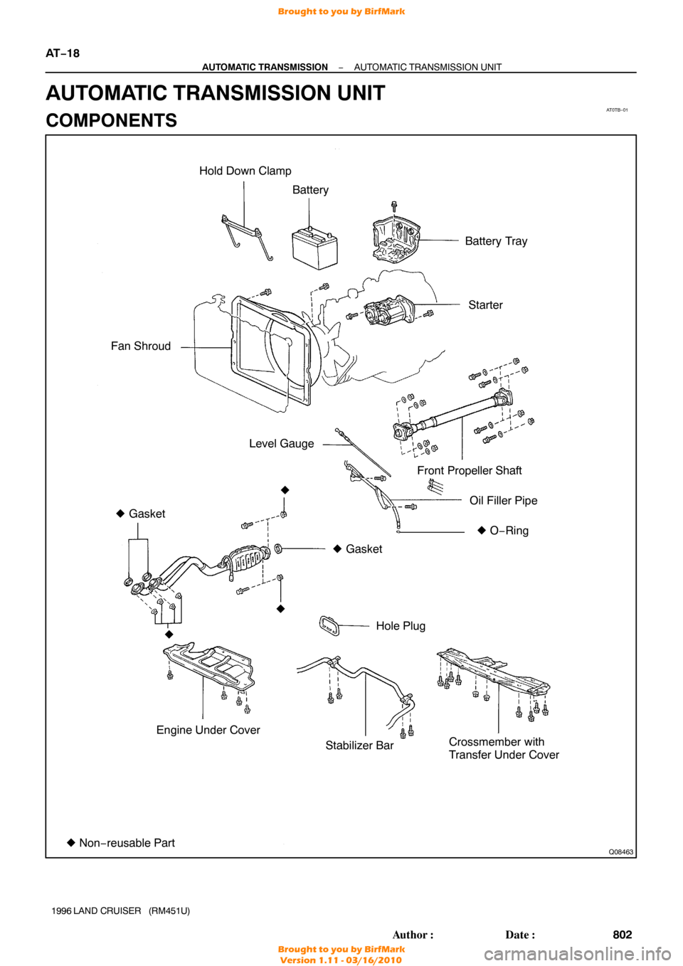
Q08463
Hold Down ClampBattery
Battery Tray
Starter
Fan Shroud
Level Gauge Front Propeller Shaft
Oil Filler Pipe
� Gasket
� Hole Plug�
O− Ring
Engine Under Cover Stabilizer BarCrossmember with
Transfer Under Cover
� Non− reusable Part �
� Gasket
�
AT
−18
−
AUTOMATIC TRANSMISSION AUTOMATIC TRANSMISSION UNIT
802
Author�: Date�:
1996 LAND CRUISER (RM451U)
AUTOMATIC TRANSMISSION UNIT
COMPONENTS
Brought to you by BirfMark
Brought to you by BirfMark
Version 1.11 - 03/16/2010
Page 141 of 1399
AT−22
−
AUTOMATIC TRANSMISSION AUTOMATIC TRANSMISSION UNIT
1996 LAND CRUISER (RM451U)
(i) Remove the 4 bolts and transfer shift lever.
Torque: 18 N·m (185 kgf·cm, 13 ft·lbf)
(j) Remove the 2 cushions.
6. DISCONNECT THESE CONNECTORS:
�No.1 vehicle speed sensor
�No.2 vehicle speed sensor
�Park/neutral position switch
�Solenoid connector
�ATF temperature sensor
�Center differential lock indicator switch
�L4 position switch
�Neutral position switch
7. DISCONNECT BLEEDER HOSE FROM TRANSFER
8. REMOVE FRONT AND REAR PROPELLER SHAFT (See page PR−3 )
9. REMOVE OIL FILLER PIPE
(a) Remove the level gauge.
(b) Remove the upper side mounting bolt.
(c) Remove the bolt and filler pipe.
HINT:
At the time of installation, replace the used O −ring with a new
one.
10. LOOSEN 2 OIL COOLER PIPE UNION NUTS
Torque: 34 N·m (350 kgf·cm, 25 ft·lbf)
Brought to you by BirfMark
Brought to you by BirfMark
Version 1.11 - 03/16/2010
Page 146 of 1399

BE1LT−01
BE−2
−
BODY ELECTRICAL BODY ELECTRICAL SYSTEM
1996 LAND CRUISER (RM451U)
PROBLEM SYMPTOMS TABLE
IGNITION SWITCH AND KEY UNLOCK WARNING SWITCH
SymptomSuspect AreaSee page
Ignition switch is not set to each position.5. Ignition SwitchBE−11
”Key unlock warning system” does not operate.
1. GAUGE Fuse (I/P F/B)
2. Key Unlock Warning Switch
3. Door Courtesy Switch
4. Wire Harness−
BE−11
BE−21 −
HEADLIGHT AND TAILLIGHT SYSTEM
SymptomSuspect AreaSee page
Headlight does not light up. (Taillight is normal.)
1. Headlight Bulb
2. MAIN FL
3. HEAD (LH) Fuse (No.2 R/B)
4. HEAD (RH) Fuse (No.2 R/B)
5. Light Control Switch
6. Headlight Dimmer Switch
7. Wire Harness−
−
−
−
BE−14
BE−14
−
Headlight does not light up. (Taillight does not light up.)
1. Headlight Bulb
2. Light Control Switch
3. Headlight Dimmer Switch
4. Wire Harness−
BE−14
BE−14 −
Only one light comes ON.
1. Headlight Bulb
2. HEAD (LH) Fuse (No.2 R/B)
3. HEAD (RH) Fuse (No.2 R/B)
4. Wire Harness−
−
−
−
”Lo− Beam” does not light up.
1. Headlight Bulb
2. Headlight Control Relay (No.2 R/B)
3. Headlight Dimmer Switch
4. Wire Harness−
−
BE−14 −
”Hi− Beam” does not light up.
1. Headlight Bulb
2. Headlight Control Relay (No.2 R/B)
3. Headlight Dimmer Switch
4. Wire Harness−
−
BE−14 −
”Flash” does not light up.
1. Headlight Bulb
2. Headlight Control Relay (No.2 R/B)
3. Headlight Dimmer Switch
4. Wire Harness−
−
BE−14 −
Taillight does not light up. (Headlight is normal.)
1. Taillight Bulb
2. TAIL Fuse (I/P F/B)
3. Light Control Switch
4. Taillight Control Relay (No.2 R/B)
5. Wire Harness−
−
BE−14
BE−14 −
Taillight does not light up. (Headlight does not light up.)
1. Taillight Bulb
2. MAIN FL
3. TAIL Fuse (I/P F/B)
4. Light Control Switch
5. Wire Harness−
−
−
BE−14 −
Headlight and Taillight does not light.1. Light Control Switch
2. Wire HarnessBE−14
−
Brought to you by BirfMark
Brought to you by BirfMark
Version 1.11 - 03/16/2010