Page 94 of 1399
AC3JN−01
−
AIR CONDITIONING FRONT BLOWER MOTOR
AC−51
1378
Author�: Date�:
1996 LAND CRUISER (RM451U)
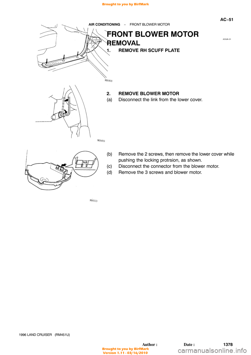
FRONT BLOWER MOTOR
REMOVAL
1. REMOVE RH SCUFF PLATE
2. REMOVE BLOWER MOTOR
(a) Disconnect the link from the lower cover.
(b) Remove the 2 screws, then remove the lower cover while
pushing the locking protrsion, as shown.
(c) Disconnect the connector from the blower motor.
(d) Remove the 3 screws and blower motor.
f'05499
f()j5oo
Brought to you by BirfMark
Brought to you by BirfMark
Version 1.11 - 03/16/2010
Page 105 of 1399
AC2SC−01
N14163
AC−62
−
AIR CONDITIONING PRESSURE SWITCH
1996 LAND CRUISER (RM451U)
REMOVAL
1. DISCHARGE REFRIGERANT FROM REFRIGERA TION
SYSTEM
HINT:
Evacuate air from refrigeration system.
Charge system with refrigerant and inspect for leakage of refrig-
erant.
Specified amount:
850 ± 50 g (29.98 ± 1.76 oz.)
2. REMOVE PRESSURE SWITCH
(a) Disconnect the connector.
(b) Remove the pressure switch from the liquid tube. Torque: 10 N·m (100 kgf·cm, 7 ft·lbf)
HINT:
At the time of installation, lubricate a new O− ring with compres-
sor oil and install the switch.
HINT:
Lock the switch mount on the tube with an open end wrench,
being careful not to deform the tube, and remove the switch.
Brought to you by BirfMark
Brought to you by BirfMark
Version 1.11 - 03/16/2010
Page 122 of 1399

SPEEDOMETER DRIVEN GEAR
ON−VEHICLE RE")
Q07268
AT0T0−01
Q07264
Z15453
SST
Z15454
SST
Q07268
−
AUTOMATIC TRANSMISSION SPEEDOMETER DRIVEN GEAR
AT−3
787
Author�: Date�:
1996 LAND CRUISER (RM451U)
SPEEDOMETER DRIVEN GEAR
ON−VEHICLE REPAIR
1. DISCONNECT SPEEDOMETER CABLE AND RE-
MOVE SPEEDOMETER DRIVEN GEAR
(a) Loosen the serrated collar with pliers. Do not lose the felt
dust protector and washer.
(b) Disconnect the speedometer cable.
(c) Remove the bolt and locking plate. Pry out the speedom-
eter driven gear assembly.
(d) Remove the O−ring from the speedometer driven gear assembly.
(e) Remove the clip and speedometer driven gear from the speedometer driven gear sleeve.
2. REMOVE SPEEDOMETER DRIVEN GEAR OIL SEAL
Using SST, remove the oil seal. SST 09921−00010
3. REINSTALL SPEEDOMETER DRIVEN GEAR OIL SEAL
Using SST, install a new oil seal. SST 09201−10000 (09201 −01080)
Drive in depth: 20 mm (0.79 in.)
4. REINSTALL SPEEDOMETER DRIVEN GEAR AND CONNECT SPEEDOMETER CABLE
(a) Install the clip and speedometer driven gear to the
speedometer driven gear sleeve.
(b) Install a new O−ring to the speedometer driven gear as- sembly.
(c) Install the speedometer driven gear.
(d) Install the locking plate with the bolt.
Torque: 16 N·m (160 kgf·cm, 12 ft·lbf)
(e) Connect the speedometer cable.
Brought to you by BirfMark
Brought to you by BirfMark
Version 1.11 - 03/16/2010
Page 125 of 1399
AT0T3−02
Q07388
AT−6
−
AUTOMATIC TRANSMISSION PARK/NEUTRAL POSITION (PNP) SWITCH
790
Author�: Date�:
1996 LAND CRUISER (RM451U)
PARK/NEUTRAL POSITION (PNP)
SWITCH
ON−VEHICLE REPAIR
1. DISCONNECT 2 OIL COOLER PIPES (See page
AT−16 )
2. DISCONNECT PARK/NEUTRAL POSITION SWITCH CONNECTOR
3. REMOVE PARK/NEUTRAL POSITION SWITCH
(a) Pry off the lock washer and remove the nut.
(b) Remove the bolt and park/neutral position switch.
4. REINSTALL PARK/NEUTRAL POSITION SWITCH
(a) Install the park/neutral position switch and bolt.
(b) Install a new lock plate and the nut. Torque: 6.9 N·m (70 kgf·cm, 61 in.·lbf)
(c) Stake the nut with the lock plate.
(d) Adjust the park/neutral position switch. (See page DI−131 )
5. RECONNECT PARK/NEUTRAL POSITION SWITCH CONNECTOR
6. RECONNECT 2 OIL COOLER PIPES (See page AT−17 )
Adjust the shift lever position. (See page DI−131)
Brought to you by BirfMark
Brought to you by BirfMark
Version 1.11 - 03/16/2010
Page 129 of 1399
AT0T5−02
AT1366
AT2000
AT2001
AT−10
−
AUTOMATIC TRANSMISSION PARKING LOCK PAWL
794
Author�: Date�:
1996 LAND CRUISER (RM451U)
PARKING LOCK PAWL
ON−VEHICLE REPAIR
1. REMOVE VALVE BODY (See page AT −7)
2. REMOVE PARKING LOCK PAWL BRACKET
3. REMOVE SPRING FROM PARKING LOCK PAWL SHAFT
4. REMOVE PARKING LOCK PAWL AND SHAFT
5. REINSTALL PARKING LOCK PAWL AND SHAFT
6. REINSTALL SPRING
7. REINSTALL PARKING LOCK PAWL BRACKET
HINT:
�Push the lock rod fully forward.
�Check that the parking lock pawl operates smoothly.
Torque: 7.4 N·m (75 kgf·cm, 65 in.·lbf)
8. REINSTALL VALVE BODY (See page AT −7)
Brought to you by BirfMark
Brought to you by BirfMark
Version 1.11 - 03/16/2010
Page 131 of 1399
AT0YZ−01
Z16651
Key Interlock Solenoid
Stop Light Switch Shift Lock Solenoid
Shift Lock Control Switch
Shift Lock Control ECU
Ignition Switch
Shift Lock
Control ECU
Stop Light
Switch
Shift Lock Solenoid
Key Interlock Solenoid
Shift Lock
Control Switch
Battery Stop
Light
MAIN
FL FL
ALT
FL
AM1
STOP ACC
IG ECU − IG CIG
IG ACC
STP P1
P2
P EKLS
SLS
−
SLS+
AT
−12
−
AUTOMATIC TRANSMISSION SHIFT LOCK SYSTEM
796
Author�: Date�:
1996 LAND CRUISER (RM451U)
SHIFT LOCK SYSTEM
LOCATION
Brought to you by BirfMark
Brought to you by BirfMark
Version 1.11 - 03/16/2010
Page 132 of 1399
Z16656
BC
KLS
E
STP SLS−
ACC
IG A
SLS+
AT0T7−04
Q07316
Ohmmeter
Q07315Battery
−
AUTOMATIC TRANSMISSION SHIFT LOCK SYSTEM
AT−13
1996 LAND CRUISER (RM451U)
INSPECTION
1. INSPECT SHIFT LOCK CONTROL ECU
Using a voltmeter, measure the voltage at each terminal.
HINT:
Do not disconnect the ECU connector.
2. INSPECT SHIFT LOCK SOLENOID
(a) Disconnect the solenoid connector.
(b) Using an ohmmeter, measure the resistance between ter-
minals.
Standard resistance: 20 − 28 Ω
If the resistance is not as specified, replace the solenoid.
(c) Apply the battery positive voltage between terminals. At this time, confirm that solenoid operate.
If the operation is not as specified, replace the solenoid.
Brought to you by BirfMark
Brought to you by BirfMark
Version 1.11 - 03/16/2010
Page 133 of 1399
Q07314
P1P2
P
AT
−14
−
AUTOMATIC TRANSMISSION SHIFT LOCK SYSTEM
1996 LAND CRUISER (RM451U)
3. INSPECT KEY INTERLOCK SOLENOID
(a) Disconnect the solenoid connector.
(b) Using an ohmmeter, measure the resistance between ter-
minals 7 and 8.
Standard resistance: 12 − 17 Ω
If the resistance is not as specified, replace the solenoid.
4. INSPECT SHIFT LOCK CONTROL SWITCH
Inspect that there is continuity between each terminal.
Shift positionTester condition to
terminal numberSpecified value
P position (Release
button is not pushed)P1 − PContinuity
P position (Release
button is pushed)P1 − P
P2 − PContinuity
R, N, D, 2, L positionP2 − PContinuity
If the continuity is not as specified, replace the switch.
Brought to you by BirfMark
Brought to you by BirfMark
Version 1.11 - 03/16/2010

REMOVAL
1. DISCHARGE REFRIGERANT FROM REFRIGERA TION
SYSTEM
HINT:
Evacuate air from refrigeration system.")


INSPECTION
1. INSPECT SHIFT LOCK CON")

3. INSPECT KEY INTERLOCK SOLENOID
(a) Disconnect the solenoid connector.
(b) Using an ohmmeter, measur")