Page 1233 of 1399
−
SFI THROTTLE BODY
SF−47
1996 LAND CRUISER (RM451U)
(b) Apply vacuum to the throttle opener.
(c) Insert a 0.62 mm (0.024 in.) feeler gauge between the
throttle stop screw and stop lever.
(d) Connect the test probe of an ohmmeter to the terminals IDL and E2 of the sensor.
(e) Gradually turn the sensor clockwise until the ohmmeter deflects, and secure it with the 2 set screws.
(f) Recheck the continuity between terminals IDL and E2.
Clearance between
lever and stop screwContinuity (IDL − E2)
0.50 mm (0.020 in.)Continuity
0.75 mm (0.030 in.)No continuity
Brought to you by BirfMark
Brought to you by BirfMark
Version 1.11 - 03/16/2010
Page 1270 of 1399

SR16E−03
−
STEERING TILT STEERING COLUMN
SR−19
1996 LAND CRUISER (RM451U)
INSTALLATION
1. INSTALL STEERING COLUMN ASSEMBLY
(a) Torque the 2 column assembly set nuts and 2 set bolts.
Torque:25 N·m (250 kgf·cm, 18 ft·lbf)
(b) Connect the 3 connectors.
2. INSTALL SLIDING YOKE SUB −ASSEMBLY
Temporarily tighten the bolt A.
3. CONNECT SLIDING YOKE SUB−ASSEMBLY
(a) Align the matchmarks on the yoke sub−assembly and
worm gear valve body shaft.
(b) Torque the bolt B. Torque: 34 N·m (350 kgf·cm, 25 ft·lbf)
(c) Torque the bolt A.
Torque: 34 N·m (350 kgf·cm, 25 ft·lbf)
4. INSTALL LINK JOINT PROTECTOR
Torque the 2 bolts. Torque: 12 N·m (120 kgf·cm, 9 ft·lbf)
5. TORQUE 4 COLUMN HOLE COVER SET BOLTS Torque: 13 N·m (130 kgf·cm, 9 ft·lbf)
6. INSTALL COMBINATION SWITCH WITH SPIRAL CABLE
(a) Tighten the 4 screws.
(b) Connect the airbag connector.
(c) Connect the 2 connectors.
7. INSTALL UPPER AND LOWER COLUMN COVERS
Tighten the 5 screws.
8. INSTALL NO.2 HEATER TO REGISTER DUCT
9. INSTALL INSTRUMENT LOWER FINISH PANEL
(a) Tighten the 4 panel set screws.
(b) Connect the hood lock control cable and fuel lid control cable.
10. CENTER SPIRAL CABLE
(a) Check that the front wheels are facing straight ahead.
(b) Turn the cable counterclockwise by hand until it becomes harder to turn the cable.
(c) Then rotate the cable clockwise about 3 turns to align the
red mark.
HINT:
The cable will rotate about 3 turns to either left or right of the
center.
Brought to you by BirfMark
Brought to you by BirfMark
Version 1.11 - 03/16/2010
Page 1281 of 1399

R12473
SR168−01
SR0097
−
STEERING STEERING WHEEL
SR−7
1058
Author�: Date�:
1996 LAND CRUISER (RM451U)
STEERING WHEEL
INSPECTION
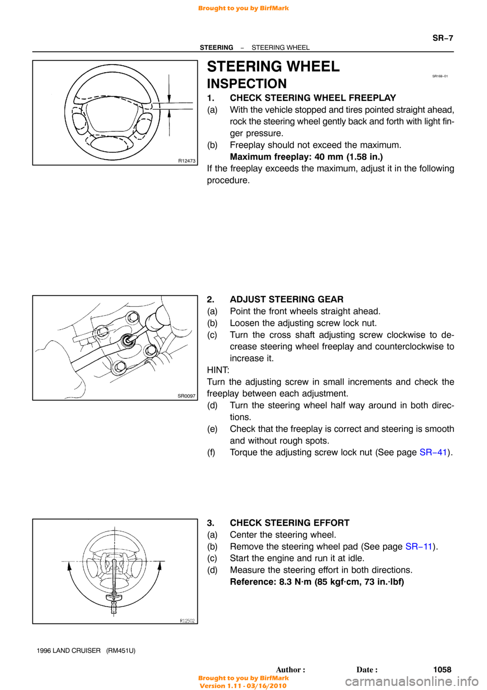
1. CHECK STEERING WHEEL FREEPLAY
(a) With the vehicle stopped and tires pointed straight ahead,
rock the steering wheel gently back and forth with light fin-
ger pressure.
(b) Freeplay should not exceed the maximum. Maximum freeplay: 40 mm (1.58 in.)
If the freeplay exceeds the maximum, adjust it in the following
procedure.
2. ADJUST STEERING GEAR
(a) Point the front wheels straight ahead.
(b) Loosen the adjusting screw lock nut.
(c) Turn the cross shaft adjusting screw clockwise to de- crease steering wheel freeplay and counterclockwise to
increase it.
HINT:
Turn the adjusting screw in small increments and check the
freeplay between each adjustment.
(d) Turn the steering wheel half way around in both direc- tions.
(e) Check that the freeplay is correct and steering is smooth and without rough spots.
(f) Torque the adjusting screw lock nut (See page SR−41).
3. CHECK STEERING EFFORT
(a) Center the steering wheel.
(b) Remove the steering wheel pad (See page SR−11).
(c) Start the engine and run it at idle.
(d) Measure the steering effort in both directions.
Reference: 8.3 N·m (85 kgf·cm, 73 in.·lbf)
Brought to you by BirfMark
Brought to you by BirfMark
Version 1.11 - 03/16/2010
Page 1289 of 1399

SR16N−01
SR−36
−
STEERING POWER STEERING GEAR
1996 LAND CRUISER (RM451U)
DISASSEMBLY
NOTICE:
When using a vise, do not overtighten it.
1. SECURE PS GEAR ASSEMBLY IN VISE
Secure the gear assembly on SST and clamp SST in a vise. SST 09630−00014 (09631 −00142)
2. REMOVE ADJUSTING SCREW LOCK NUT AND SEAL
WASHER
3. REMOVE SIDE COVER
(a) Remove the 4 bolts.
(b) Turn the cross shaft adjusting screw clockwise until the cover comes off.
(c) Remove the O−ring from the cover.
4. REMOVE CROSS SHAFT
Using a plastic hammer, tap on the cross shaft end and pull out
the shaft.
5. REMOVE POWER PISTON PLUNGER GUIDE NUT, COMPRESSION SPRING, POWER PISTON PLUNGER
AND POWER PISTON PLUNGER GUIDE
(a) Using a hexagon wrench (10 mm), remove the plunger
guide nut.
(b) Remove the O−ring from the plunger guide nut.
6. REMOVE WORM GEAR VALVE BODY ASSEMBLY
(a) Remove the 4 bolts.
(b) Using SST, turn the valve body shaft clockwise with hold-
ing the worm gear by your finger so it cannot move.
SST 09616−00010
Brought to you by BirfMark
Brought to you by BirfMark
Version 1.11 - 03/16/2010
Page 1354 of 1399

P21088
OhmmeterNo Continuity
P10821
Lock
Free
−
STARTING STARTER
ST−9
1996 LAND CRUISER (RM451U)
Minimum spring installed load:
1.4 kW type: 11.8 N (1.20 kgf, 2.7 lbf)
2.0 kW type: 12.7 N (1.29 kgf, 2.9 lbf)
If the installed load is less than minimum replace the brush
springs.
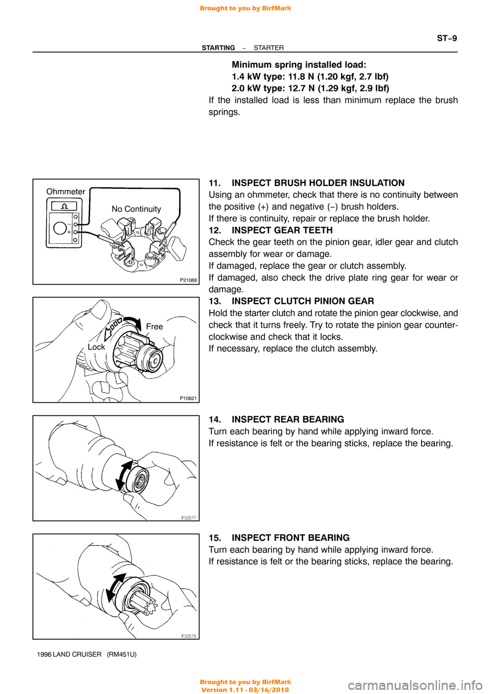
11. INSPECT BRUSH HOLDER INSULATION
Using an ohmmeter, check that there is no continuity between
the positive (+) and negative ( −) brush holders.
If there is continuity, repair or replace the brush holder.
12. INSPECT GEAR TEETH
Check the gear teeth on the pinion gear, idler gear and clutch
assembly for wear or damage.
If damaged, replace the gear or clutch assembly.
If damaged, also check the drive plate ring gear for wear or
damage.
13. INSPECT CLUTCH PINION GEAR
Hold the starter clutch and rotate the pinion gear clockwise, and
check that it turns freely. Try to rotate the pinion gear counter-
clockwise and check that it locks.
If necessary, replace the clutch assembly.
14. INSPECT REAR BEARING
Turn each bearing by hand while applying inward force.
If resistance is felt or the bearing sticks, replace the bearing.
15. INSPECT FRONT BEARING
Turn each bearing by hand while applying inward force.
If resistance is felt or the bearing sticks, replace the bearing.
Brought to you by BirfMark
Brought to you by BirfMark
Version 1.11 - 03/16/2010