Page 209 of 1399

−
BODY ELECTRICAL POWER SEAT CONTROL SYSTEM
BE−65
1996 LAND CRUISER (RM451U)
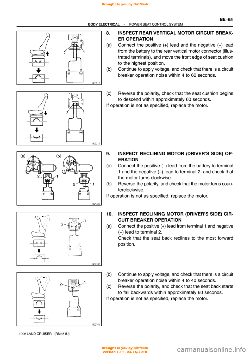
8. INSPECT REAR VERTICAL MOTOR CIRCUIT BREAK-
ER OPERATION
(a) Connect the positive (+) lead and the negative ( −) lead
from the battery to the rear vertical motor connector (illus-
trated terminals), and move the front edge of seat cushion
to the highest position.
(b) Continue to apply voltage, and check that there is a circuit
breaker operation noise within 4 to 60 seconds.
(c) Reverse the polarity, check that the seat cushion begins to descend within approximately 60 seconds.
If operation is not as specified, replace the motor.
9. INSPECT RECLINING MOTOR (DRIVER’S SIDE) OP- ERATION
(a) Connect the positive (+) lead from the battery to terminal 1 and the negative ( −) lead to terminal 2, and check that
the motor turns clockwise.
(b) Reverse the polarity, and check that the motor turns coun-
terclockwise.
If operation is not as specified, replace the motor.
10. INSPECT RECLINING MOTOR (DRIVER’S SIDE) CIR- CUIT BREAKER OPERATION
(a) Connect the positive (+) lead from terminal 1 and negative
(−) lead to terminal 2.
Check that the seat back reclines to the most forward
position.
(b) Continue to apply voltage, and check that there is a circuit breaker operation noise within 4 to 40 seconds.
(c) Reverse the polarity, and check that the seat back starts
to fall backwards within approximately 60 seconds.
If operation is not as specified, replace the motor.
Brought to you by BirfMark
Brought to you by BirfMark
Version 1.11 - 03/16/2010
Page 210 of 1399

BE−66
−
BODY ELECTRICAL POWER SEAT CONTROL SYSTEM
1996 LAND CRUISER (RM451U)
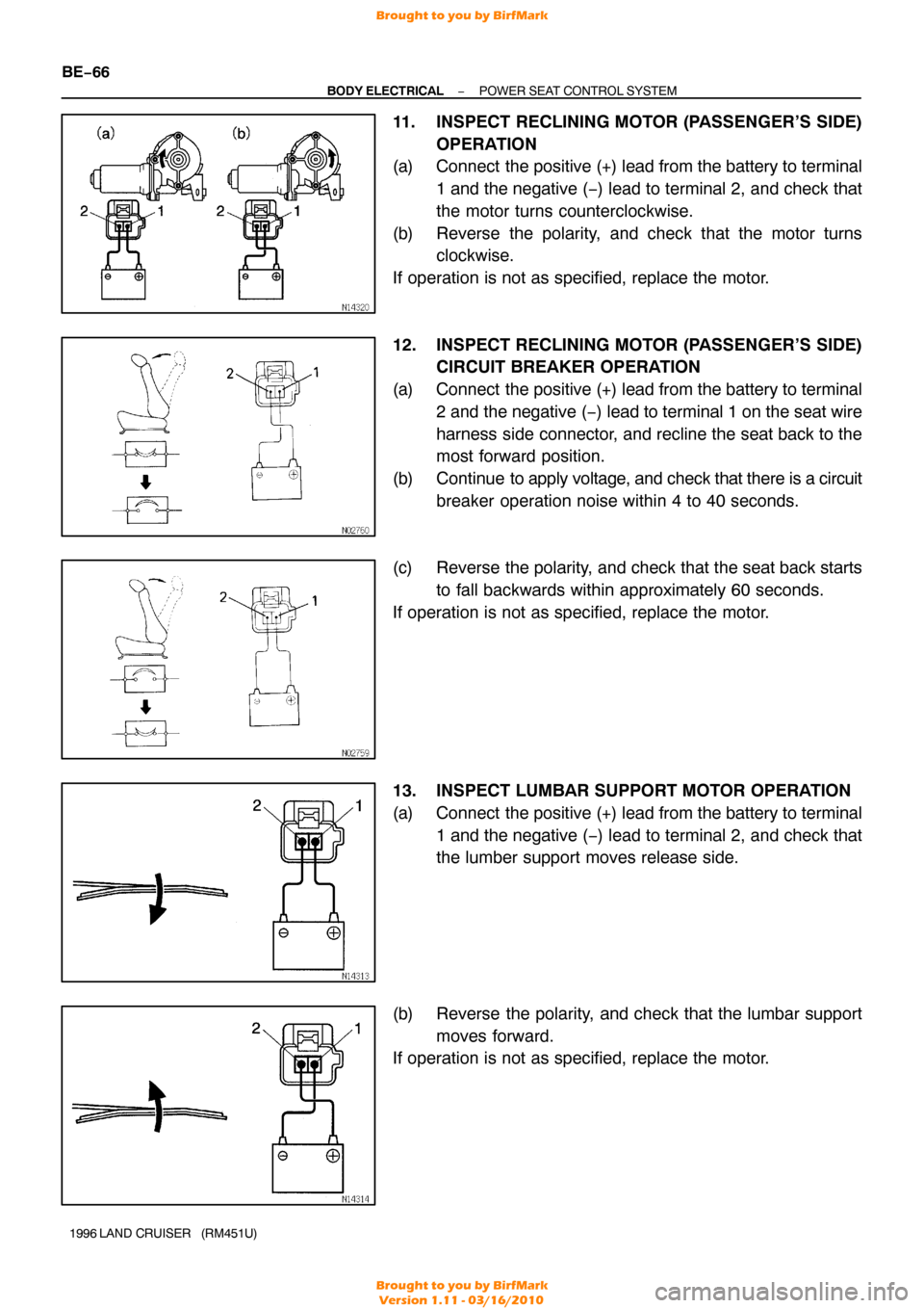
11. INSPECT RECLINING MOTOR (PASSENGER’S SIDE)
OPERATION
(a) Connect the positive (+) lead from the battery to terminal
1 and the negative ( −) lead to terminal 2, and check that
the motor turns counterclockwise.
(b) Reverse the polarity, and check that the motor turns clockwise.
If operation is not as specified, replace the motor.
12. INSPECT RECLINING MOTOR (PASSENGER’S SIDE) CIRCUIT BREAKER OPERATION
(a) Connect the positive (+) lead from the battery to terminal 2 and the negative ( −) lead to terminal 1 on the seat wire
harness side connector, and recline the seat back to the
most forward position.
(b) Continue to apply voltage, and check that there is a circuit breaker operation noise within 4 to 40 seconds.
(c) Reverse the polarity, and check that the seat back starts to fall backwards within approximately 60 seconds.
If operation is not as specified, replace the motor.
13. INSPECT LUMBAR SUPPORT MOTOR OPERATION
(a) Connect the positive (+) lead from the battery to terminal 1 and the negative ( −) lead to terminal 2, and check that
the lumber support moves release side.
(b) Reverse the polarity, and check that the lumbar support moves forward.
If operation is not as specified, replace the motor.
Brought to you by BirfMark
Brought to you by BirfMark
Version 1.11 - 03/16/2010
Page 239 of 1399
BE1MT−01
−
BODY ELECTRICAL CLOCK
BE−95
1233
Author�: Date�:
1996 LAND CRUISER (RM451U)
CLOCK
TROUBLESHOOTING
HINT:
Troubleshoot the lock according to the table below.
Clock will not operate1
Clock loses or gains time2
1.5 seconds/day
Brought to you by BirfMark
Brought to you by BirfMark
Version 1.11 - 03/16/2010
Page 240 of 1399
BE−96
−
BODY ELECTRICAL CLOCK
1234
Author�: Date�:
1996 LAND CRUISER (RM451U)
Brought to you by BirfMark
Brought to you by BirfMark
Version 1.11 - 03/16/2010
Page 316 of 1399
BO398−01
BO−76
−
BODY INSTRUMENT PANEL
1996 LAND CRUISER (RM451U)
REMOVAL
1. REMOVE STEERING WHEEL (See page SR−11)
2. REMOVE COLUMN COVER
3. REMOVE HOOD LOCK RELEASE LEVER
4. REMOVE FUEL LID RELEASE LEVER
5. REMOVE FUSE BOX OPENING COVER
6. REMOVE LOWER FINISH PANEL
7. REMOVE LOWER INSTRUMENT PANEL
8. REMOVE NO. 2 HEATER TO REGISTER DUCT
9. LOOSEN DLC 3 AND FUSE BLOCK
10. REMOVE NO. 2 CENTER CLUSTER FINISH PANEL
11. REMOVE STEERING COLUMN (See page SR−11)
12. REMOVE CLUSTER FINISH PANEL
13. REMOVE COMBINATION METER
14. REMOVE CENTER CLUSTER FINISH PANEL WITH CLOCK
Brought to you by BirfMark
Brought to you by BirfMark
Version 1.11 - 03/16/2010
Page 412 of 1399
P03807
HoldSST (B)
SST (A)
Turn
P08242
SST (C)
CH−10
−
CHARGING GENERATOR
1996 LAND CRUISER (RM451U)
4. REMOVE RECTIFIER HOLDER
(a) Remove the 4 screws and rectifier holder.
(b) Remove the 4 rubber insulators.
(c) Remove the seal plate.
5. REMOVE PULLEY
(a) Hold SST (A) with a torque wrench, and tighten SST (B)
clockwise to the specified torque.
SST 09820−63010
Torque: 39 N·m (400 kgf·cm, 29 ft·lbf)
(b) Check that SST (A) is secured to the rotor shaft.
(c) Mount SST (C) in a vise.
(d) Install the generator to SST (C).
Brought to you by BirfMark
Brought to you by BirfMark
Version 1.11 - 03/16/2010
Page 418 of 1399
P03802
CH06M−03
P03794
P03807
Hold SST (A)
SST (B)
Turn
P08242
SST (C)
CH−16
−
CHARGING GENERATOR
1996 LAND CRUISER (RM451U)
REASSEMBLY
1. PLACE RECTIFIER END FRAME ON PULLEY
2. INSTALL ROTOR TO DRIVE END FRAME
3. INSTALL RECTIFIER END FRAME
(a) Place the generator washer on the rotor.
(b) Using a 29 mm socket wrench and press, slowly press in
the rectifier end frame.
(c) Install the 4 nuts. Torque: 4.5 N·m (46 kgf·cm, 40 in.·lbf)
4. INSTALL PULLEY
(a) Install the pulley to the rotor shaft by tightening the pulley
nut by hand.
(b) Hold SST (A) with a torque wrench, and tighten SST (B)
clockwise to the specified torque.
SST 09820−63010
Torque: 39 N·m (400 kgf·cm, 29 ft·lbf)
(c) Check that SST (A) is secured to the pulley shaft.
(d) Mount SST (C) in a vise.
(e) Install the generator to SST (C).
Brought to you by BirfMark
Brought to you by BirfMark
Version 1.11 - 03/16/2010
Page 820 of 1399

−
ENGINE MECHANICAL CYLINDER HEAD
EM−35
1996 LAND CRUISER (RM451U)
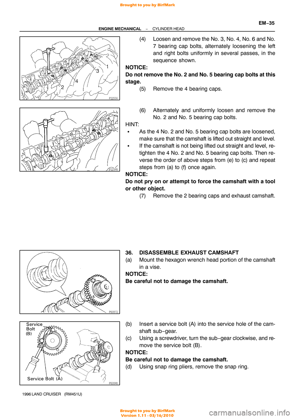
(4) Loosen and remove the No. 3, No. 4, No. 6 and No.
7 bearing cap bolts, alternately loosening the left
and right bolts uniformly in several passes, in the
sequence shown.
NOTICE:
Do not remove the No. 2 and No. 5 bearing cap bolts at this
stage. (5) Remove the 4 bearing caps.
(6) Alternately and uniformly loosen and remove theNo. 2 and No. 5 bearing cap bolts.
HINT:
�As the 4 No. 2 and No. 5 bearing cap bolts are loosened,
make sure that the camshaft is lifted out straight and level.
�If the camshaft is not being lifted out straight and level, re-
tighten the 4 No. 2 and No. 5 bearing cap bolts. Then re-
verse the order of above steps from (e) to (c) and repeat
steps from (a) to (f) once again.
NOTICE:
Do not pry on or attempt to force the camshaft with a tool
or other object.
(7) Remove the 2 bearing caps and exhaust camshaft.
36. DISASSEMBLE EXHAUST CAMSHAFT
(a) Mount the hexagon wrench head portion of the camshaft in a vise.
NOTICE:
Be careful not to damage the camshaft.
(b) Insert a service bolt (A) into the service hole of the cam-
shaft sub−gear.
(c) Using a screwdriver, turn the sub− gear clockwise, and re-
move the service bolt (B).
NOTICE:
Be careful not to damage the camshaft.
(d) Using snap ring pliers, remove the snap ring.
Brought to you by BirfMark
Brought to you by BirfMark
Version 1.11 - 03/16/2010