Page 1243 of 1399

SF1F7−01
P09134
OhmmeterContinuity
Ohmmeter Ohmmeter
Continuity
No Continuity FP
PR
FPR
+B1
+B2
P09135
Ohmmeter
No
Continuity
Battery
Ohmmeter
Continuity +B1
+B2 FP
PR
FPR
−
SFI FUEL PUMP RELAY
SF−57
685
Author�: Date�:
1996 LAND CRUISER (RM451U)
FUEL PUMP RELAY
INSPECTION
1. REMOVE FUEL PUMP RELAY
(a) Disconnect the fuel pump relay connector.
(b) Remove the bolt and fuel pump relay.
2. INSPECT FUEL PUMP RELAY CONTINUITY
(a) Using an ohmmeter, check that there is continuity be-
tween terminals +B1 and FPR.
(b) Check that there is continuity between terminals +B2 and
FP.
(c) Check that there is no continuity between terminals +B2
and PR.
If continuity is not as specified, replace the relay.
3. INSPECT FUEL PUMP RELAY OPERATION
(a) Apply battery voltage across terminals +B1 and FPR.
(b) Using an ohmmeter, check that there is no continuity be- tween the +B2 and FP.
(c) Check that there is continuity between terminals +B2 and
PR.
If operation is not as specified, replace the relay.
4. REINSTALL FUEL PUMP RELAY
Brought to you by BirfMark
Brought to you by BirfMark
Version 1.11 - 03/16/2010
Page 1245 of 1399
SF1F9−01
−
SFI VSV FOR FUEL PRESSURE CONTROL
SF−59
687
Author�: Date�:
1996 LAND CRUISER (RM451U)
VSV FOR FUEL PRESSURE
CONTROL
INSPECTION
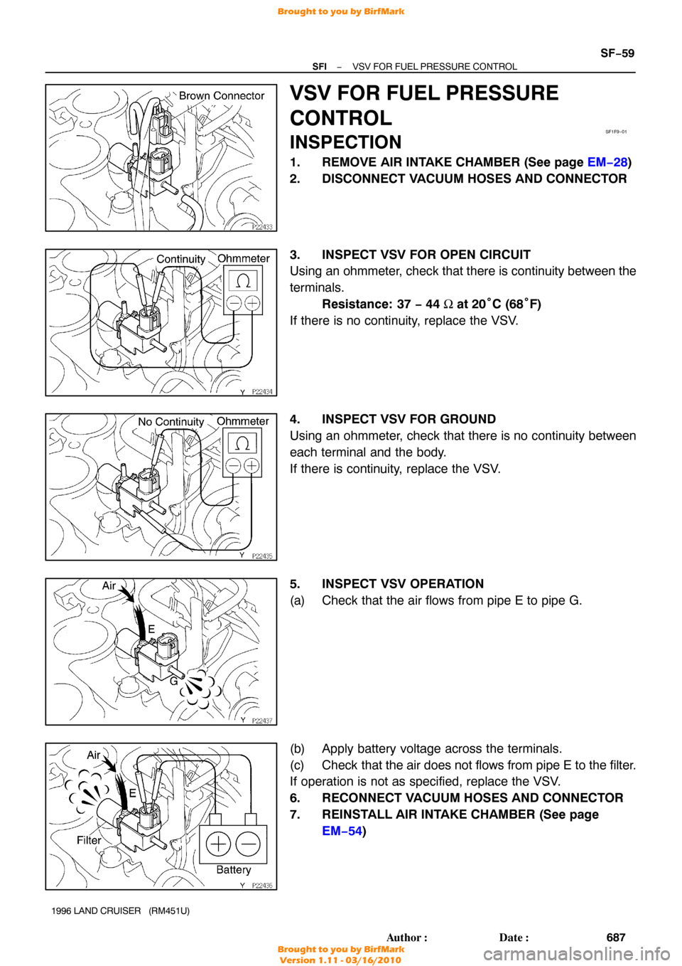
1. REMOVE AIR INTAKE CHAMBER (See page EM−28 )
2. DISCONNECT VACUUM HOSES AND CONNECTOR
3. INSPECT VSV FOR OPEN CIRCUIT
Using an ohmmeter, check that there is continuity between the
terminals. Resistance: 37 − 44 Ω at 20° C (68°F)
If there is no continuity, replace the VSV.
4. INSPECT VSV FOR GROUND
Using an ohmmeter, check that there is no continuity between
each terminal and the body.
If there is continuity, replace the VSV.
5. INSPECT VSV OPERATION
(a) Check that the air flows from pipe E to pipe G.
(b) Apply battery voltage across the terminals.
(c) Check that the air does not flows from pipe E to the filter.
If operation is not as specified, replace the VSV.
6. RECONNECT VACUUM HOSES AND CONNECTOR
7. REINSTALL AIR INTAKE CHAMBER (See page EM−54 )
Brought to you by BirfMark
Brought to you by BirfMark
Version 1.11 - 03/16/2010
Page 1248 of 1399
SF1FB−01
P01630
Ohmmeter
SF−62
−
SFI KNOCK SENSOR
690
Author�: Date�:
1996 LAND CRUISER (RM451U)
KNOCK SENSOR
INSPECTION
1. REMOVE KNOCK SENSOR
(a) Disconnect the knock sensor connector.
(b) Using SST, remove the knock sensor.
SST 09816−30010
2. INSPECT KNOCK SENSOR
Using an ohmmeter, check that there is no continuity between
the terminal and body.
If there is continuity, replace the sensor.
3. REINSTALL KNOCK SENSOR
(a) Using SST, install the knock sensor. SST 09816−30010
Torque: 44 N·m (450 kgf·cm, 33 ft·lbf)
(b) Connect the knock sensor connector.
Brought to you by BirfMark
Brought to you by BirfMark
Version 1.11 - 03/16/2010
Page 1305 of 1399

ENGINE MECHANICAL
SERVICE DATA
Compression
pressureat 250 rpm STD
Minimum
Difference of")
SS1EO−04
SS−4
−
SERVICE SPECIFICATIONS ENGINE MECHANICAL
127
Author�: Date�:
1996 LAND CRUISER (RM451U)
ENGINE MECHANICAL
SERVICE DATA
Compression
pressureat 250 rpm STD
Minimum
Difference of pressure between each cylinder1,176 kPa (12.0 kgf/cm2, 171 psi) or more
883 kPa (9.0 kgf/cm2, 128 psi)
98 kPa (1.0 kgf/cm2, 14 psi) or less
Valve clearanceat cold Intake Exhaust0.15 − 0.25 mm (0.006 − 0.010 in.)
0.25 − 0.35 mm (0.010 − 0.014 in.)
Ignition timingw/ Terminals TE1 and E1 connected3° BTDC @ idle
Idle speed−650 ± 50 rpm
Cylinder headWarpage
Cylinder block side Maximum
Manifold side Maximum
Valve seat
Refacing angle Intake
Exhaust
Contacting angle
Contacting width Intake
Exhaust
Cylinder head bolt outside diameter STD
Minimum
0.15 mm (0.0059 in.)
0.10 mm (0.0039 in.)
30°, 45° , 75°
45 °, 75°
45 °
1.2 − 1.6 mm (0.047 − 0.063 in.)
1.0 − 1.4 mm (0.039 − 0.055 in.)
10.85 − 11.00 mm (0.4272 − 0.4331 in.)
10.6 mm (0.417 in.)
Valve guide
bushingInside diameter
Outside diameter (for repair part) STD O/S 0.05
Protrusion height7.010 − 7.030 mm (0.2760 − 0.2768 in.)
11.492 − 11.513 mm (0.4524 − 0.4533 in.)
11.542 − 11.563 mm (0.4544 − 0.4522 in.)
8.2 − 8.6 mm (0.323 − 0.339 in.)
ValveValve overall length STD Intake
Exhaust
Minimum Intake Exhaust
Valve face angle
Stem diameter Intake
Exhaust
Stem oil clearance STD Intake
Exhaust
Maximum Intake
Exhaust
Margin thickness STD
Minimum98.4 mm (3.874 in.)
97.9 mm (3.854 in.)
97.9 mm (3.854 in.)
97.4 mm (3.835 in.)
44.5 °
6.970 − 6.985 mm (0.2744 − 0.2750 in.)
6.965 − 6.980 mm (0.2742 − 0.2748 in.)
0.025 − 0.060 mm (0.0010 − 0.0024 in.)
0.030 − 0.065 mm (0.0012 − 0.0026 in.)
0.08 mm (0.0031 in.)
0.10 mm (0.0039 in.)
1.2 mm (0.047 in.)
1.0 mm (0.039 in.)
Valve springDeviation Maximum
Free length
Installed tension at 36.5 mm (1.437 in.)2.0 mm (0.079 in.)
43.94 − 45.06 mm (1.7299 − 1.7740 in.)
214 − 238 N (21.8 − 24.2 kgf, 48.1 − 53.4 lbf)
Valve lifterLifter diameter
Lifter bore diameter
Oil clearance STD
Maximum33.966 − 33.976 mm (1.3372 − 1.3376 in.)
34.000 − 34.021 mm (1.3386 − 1.3394 in.)
0.024 − 0.055 mm (0.0009 − 0.0022 in.)
0.07 mm (0.0028 in.)
ManifoldWarpage Maximum0.30 mm (0.0118 in.)
Air intake chamberWarpageMaximum0.30 mm (0.0118 in.)
Brought to you by BirfMark
Brought to you by BirfMark
Version 1.11 - 03/16/2010
Page 1321 of 1399
SS1F1−04
SS−20
−
SERVICE SPECIFICATIONS STARTING
1996 LAND CRUISER (RM451U)
TORQUE SPECIFICATION
Part tightenedN·mkgf·cmft·lbf
Starter mounting bolt3940029
Starter wire mounting nut8.89078 in.·lbf
Terminal bolt x Terminal C1717312.5
Terminal bolt x Terminal 301717312.5
End cover x Magnetic housing 1.4 kW
2.0 kW2.5
3.625
3722 in.·lbf
32 in.·lbf
End cover x Field frame 1.4 kW
2.0 kW1.5
3.815
4013 in.·lbf
35 in.·lbf
Starter hosing x Magnetic switch 1.4 kW
2.0 kW5.9
9.360
9552 in.·lbf
82 in.·lbf
Field frame x Armature assembly 1.4 kW
2.0 kW5.9
9.360
9552 in.·lbf
82 in.·lbf
Lead wire x Terminal C of starter5.96052 in.·lbf
Brought to you by BirfMark
Brought to you by BirfMark
Version 1.11 - 03/16/2010
Page 1323 of 1399
SS1F3−04
SS−22
−
SERVICE SPECIFICATIONS CHARGING
1996 LAND CRUISER (RM451U)
TORQUE SPECIFICATION
Part tightenedN·mkgf·cmft·lbf
Bearing retainer x Drive end frame2.62723 in.·lbf
Rectifier end frame x Drive end frame4.54640 in.·lbf
Generator pulley x Rotor11 01,12581
Rectifier x Rectifier holder2.93025 in.·lbf
Rear end cover x Rectifier holder4.44539 in.·lbf
Rectifier plate x Rectifier holder3.83934 in.·lbf
Terminal insulator x Rectifier holder4.14236 in.·lbf
Drive belt adjusting bar x Timing chain cover2121015
Generator x Generator bracket5960043
Drive belt adjusting bar x Generator2121015
Brought to you by BirfMark
Brought to you by BirfMark
Version 1.11 - 03/16/2010
Page 1327 of 1399

Center differential side gear thrust washer thickness
1.70 mm (0.0669 in.)
1.85 mm (0.0728 in.)
2.00 mm (0.")
SS−26
−
SERVICE SPECIFICATIONS TRANSFER
149
Author�: Date�:
1996 LAND CRUISER (RM451U)
Center differential side gear thrust washer thickness
1.70 mm (0.0669 in.)
1.85 mm (0.0728 in.)
2.00 mm (0.0787 in.)
2.15 mm (0.0846 in.)
2.30 mm (0.0906 in.)
2.45 mm (0.0965 in.)
2.60 mm (0.1024 in.)
2.75 mm (0.1083 in.)
2.90 mm (0.1142 in.)
3.05 mm (0.1201 in.)
Front drive gear piece snap ring thickness
Mark A
B
C
D E
F
G H J
K
L2.00 mm (0.0787 in.)
2.10 mm (0.0827 in.)
2.20 mm (0.0866 in.)
2.30 mm (0.0906 in.)
2.40 mm (0.0945 in.)
2.50 mm (0.0984 in.)
2.60 mm (0.1024 in.)
2.70 mm (0.1063 in.)
2.80 mm (0.1102 in.)
1.80 mm (0.0709 in.)
1.90 mm (0.0748 in.)
Front extension housing ball bearing snap ring thickness Mark A
B1.7 mm (0.0669 in.)
1.8 mm (0.0709 in.)
Front output shaft hub snap ring thickness Mark A
B
C
D E1.8 mm (0.0709 in.)
1.9 mm (0.0748 in.)
2.0 mm (0.0787 in.)
2.1 mm (0.0827 in.)
2.2 mm (0.0866 in.)
Oil pump driven rotor body clearance STD
Max.0.08 − 0.17 mm (0.0031 − 0.0067 in.)
0.17 mm (0.0067 in.)
Oil pump driven rotor body tip clearance STD
Max.0.05 − 0.15 mm (0.0020 − 0.0059 in.)
0.15 mm (0.0059 in.)
Oil pump side clearance STD
Max.0.03 − 0.10 mm (0.0012 − 0.0039 in.)
0.10 mm (0.0039 in.)
Rear extension housing ball bearing snap ring thickness Mark A
B1.7 mm (0.0669 in.)
1.8 mm (0.0709 in.)
Rear output shaft ball bearing snap ring thickness Mark 1
2
3
41.95 mm (0.0768 in.)
2.05 mm (0.0807 in.)
2.15 mm (0.0847 in.)
2.25 mm (0.0886 in.)
Motor actuator
Terminal 2 − Terminal 3 STD resistance
Terminal 2 or 3 − Body ground STD resistance
0.3 − 100 Ω
More than 0.5 MΩ
Brought to you by BirfMark
Brought to you by BirfMark
Version 1.11 - 03/16/2010
Page 1350 of 1399

DISASSEMBLY
HINT:
At the time of reassembly, use high−temperature grease to lu-
bricate the bearings,")
ST0KQ−01
P23005
P23006
P08385
P23007
−
STARTING STARTER
ST−5
1996 LAND CRUISER (RM451U)
DISASSEMBLY
HINT:
At the time of reassembly, use high−temperature grease to lu-
bricate the bearings, gears, return spring and steel ball when
assembling the starter.
1. REMOVE FIELD FRAME AND ARMATURE
(a) Remove the nut, and disconnect the lead wire from the
magnetic switch terminal.
Torque: 5.9 N·m (60 kgf·cm, 52 in.·lbf)
(b) Remove the 2 through bolts. Torque:
1.4 kW type: 5.9 N·m (60 kgf·cm, 52 in.·lbf)
2.0 kW type: 9.3 N·m (95 kgf·cm, 82 in.·lbf)
(c) Pull out the field frame with the armature from the magnet-
ic switch assembly.
(d) Remove the O−ring.
HINT:
At the time of reassembly, use a new O−ring.
HINT:
At the time of reassembly, align the protrusion of the field frame
with cutout of the magnetic switch.
2. REMOVE STARTER HOUSING, CLUTCH ASSEMBLY AND GEAR
(a) Remove the 2 screws.
Torque:
1.4 kW type: 5.9 N·m (60 kgf·cm, 52 in.·lbf)
2.0 kW type: 9.3 N·m (95 kgf·cm, 82 in.·lbf)
Brought to you by BirfMark
Brought to you by BirfMark
Version 1.11 - 03/16/2010


TORQUE SPECIFICATION
Part tightenedN·mkgf·cmft·lbf
Starter mounting bolt3940029
Starter wire mounting nut8.89078")

TORQUE SPECIFICATION
Part tightenedN·mkgf·cmft·lbf
Bearing retainer x Drive end frame2.62723 in.·lbf
Rectifier")