Page 815 of 1399

EM−30
−
ENGINE MECHANICAL CYLINDER HEAD
1996 LAND CRUISER (RM451U)
(b) Disconnect the connectors.
(1) Disconnect the knock sensor connector.
(2) Disconnect the oil level sensor connector.
(3) Disconnect the 2 connectors from the transmission.
(4) Disconnect the starter connector.
(c) Disconnect the 2 heated oxygen sensor connectors.
(d) Disconnect the PNP switch connector.
(e) Remove the 2 bolts and disconnect the engine wire from the intake manifold and cylinder block.
(f) Disconnect the PCV hose from the PCV valve.
(g) Remove the bolt holding the engine wire to the intake manifold.
(h) Disconnect the connectors. (1) Disconnect the connector for the emission controlvalve set assembly.
(2) Disconnect the 3 injector connectors.
(i) Disconnect the engine wire clamp.
(j) Disconnect the engine wire clamp.
(k) Disconnect the connectors.
(1) Disconnect the 3 injector connectors.
(2) Disconnect the EGR gas temp. sensor connector.
(l) Disconnect the clamp of the No. 6 injector wire from the bracket.
(m) Disconnect the engine wire from the cylinder head and in-
take manifold.
25. DISCONNECT NO. 2 WATER BYPASS PIPE
Remove the 3 bolts, and disconnect the bypass pipe from the
cylinder head.
Brought to you by BirfMark
Brought to you by BirfMark
Version 1.11 - 03/16/2010
Page 847 of 1399

EM−62
−
ENGINE MECHANICAL CYLINDER HEAD
1996 LAND CRUISER (RM451U)
(h) Connect the engine wire to the intake manifold and cylin-
der block with the 2 bolts.
(i) Connect the PNP switch connector.
(j) Connect the 2 heated oxygen sensor connectors.
(k) Connect the connectors.
(1) Connect the Knock sensor connector.
(2) Connect the oil level sensor connector.
(3) Connect the 2 connectors to tthe ransmission.
(4) Connect the starter connector.
(l) Connect the engine wire to the cylinder block with the bolt.
(m) Connect the connectors.
(1) Connect the ECT sender gauge connector.
(2) Connect the ECT cut switch connector.
(3) Connect the ECT sensor connector.
(4) Connect the knock sensor connector.
(5) Connect the crankshaft position sensor connector.
19. CONNECT FUEL INLET HOSE
Connect the fuel inlet hose to the fuel filter with 2 new gaskets
and the union bolt. Torque: 29 N·m (300 kgf·cm, 22 ft·lbf)
20. INSTALL INTAKE MANIFOLD STAY
Install the intake manifold stay with the 2 bolts. Torque: 36 N·m (360 kgf·cm, 26 ft·lbf)
21. INSTALL OIL DIPSTICKS AND GUIDES FOR ENGINE AND TRANSMISSION
(a) Install a new O−ring to the dipstick guide.
(b) Apply a light coat of engine oil on the O −ring.
(c) Push in the dipstick guide into the guide hole of the oil pan.
(d) Install the dipstick guide with the 2 bolts. Torque: 20 N·m (200 kgf·cm, 14 ft·lbf)
22. INSTALL THROTTLE BODY (See page SF−48)
23. INSTALL GENERATOR AND DRIVE BELTS (See page CH−19 )
Brought to you by BirfMark
Brought to you by BirfMark
Version 1.11 - 03/16/2010
Page 855 of 1399

EM−70
−
ENGINE MECHANICAL ENGINE UNIT
1996 LAND CRUISER (RM451U)
13. DISCONNECT ENGINE WIRE AND HEATER VALVE
FROM COWL PANEL
(a) Remove the 2 bolts and disconnect the engine wire and
ground strap.
(b) Remove the 2 bolts and disconnect the heater valve.
14. DISCONNECT BRAKE BOOSTER VACUUM HOSE
15. DISCONNECT EVAP HOSE
16. DISCONNECT FUEL HOSES
(a) Disconnect the fuel return hose.
(b) Remove the union bolt and 2 gaskets, and disconnect the
fuel inlet hose from the fuel filter.
17. DISCONNECT WIRES AND CONNECTORS
(a) Disconnect the 2 heated oxygen sensor connectors.
(b) Disconnect the DLC1 clamp.
(c) Disconnect the 2 oil pressure gauge connectors.
(d) Disconnect the generator wire and connector.
(e) Disconnect the connector on the intake manifold from the
fender apron.
(f) Disconnect the high−tension cord from the ignition coil.
(g) Disconnect the ground strap from the No. 1 engine hang-
er.
(h) Disconnect the ground strap from the air intake chamber.
(i) Disconnect the starter wire.
(j) Disconnect the ground cable from the cylinder block.
18. DISCONNECT A/C COMPRESSOR AND BRACKET
(a) Loosen the idler pulley nut and adjusting bolt, and remove
the drive belt.
(b) Remove the 4 mounting bolts, and disconnect the com-
pressor from the bracket.
HINT:
Put aside the compressor, and suspend it.
(c) Remove the 5 bolts and A/C compressor bracket.
19. REMOVE RADIATOR PIPE
(a) Remove the 2 nuts holding the radiator pipe to the No. 1 oil pan.
(b) Disconnect the No. 2 radiator hose from the water inlet and remove the radiator pipe.
Brought to you by BirfMark
Brought to you by BirfMark
Version 1.11 - 03/16/2010
Page 860 of 1399
P22609
−
ENGINE MECHANICAL ENGINE UNIT
EM−75
1996 LAND CRUISER (RM451U)
33. REMOVE STARTER
(a) Disconnect the starter connector.
(b) Remove the 2 bolts and starter.
34. REMOVE A/T OIL COOLER PIPES FOR TRANSMIS-
SION
(a) Remove the 3 clamp mounting bolts.
(b) Loosen the 2 union nuts, and remove the oil cooler pipes.
35. DISCONNECT THROTTLE CABLE FROM THROTTLE BODY
36. REMOVE HOLE PLUG
37. REMOVE 6 TORQUE CONVERTER CLUTCH MOUNT- ING BOLT
Turn the crankshaft to gain access to each bolt. Remove the 6
bolts.
38. REMOVE TRANSMISSION FROM ENGINE
Remove the 10 bolts and transmission.
Brought to you by BirfMark
Brought to you by BirfMark
Version 1.11 - 03/16/2010
Page 861 of 1399

EM1EE−02
EM−76
−
ENGINE MECHANICAL ENGINE UNIT
1996 LAND CRUISER (RM451U)
INSTALLATION
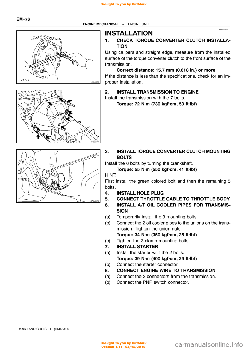
1. CHECK TORQUE CONVERTER CLUTCH INSTALLA- TION
Using calipers and straight edge, measure from the installed
surface of the torque converter clutch to the front surface of the
transmission. Correct distance: 15.7 mm (0.618 in.) or more
If the distance is less than the specifications, check for an im-
proper installation.
2. INSTALL TRANSMISSION TO ENGINE
Install the transmission with the 7 bolts. Torque: 72 N·m (730 kgf·cm, 53 ft·lbf)
3. INSTALL T ORQUE CONVERTER CLUTCH MOUNTING
BOLTS
Install the 6 bolts by turning the crankshaft. Torque: 55 N·m (550 kgf·cm, 41 ft·lbf)
HINT:
First install the green colored bolt and then the remaining 5
bolts.
4. INSTALL HOLE PLUG
5. CONNECT THROTTLE CABLE TO THROTTLE BODY
6. INSTALL A/T OIL COOLER PIPES FOR TRANSMIS-
SION
(a) Temporarily install the 3 mounting bolts.
(b) Connect the 2 oil cooler pipes to the unions on the trans-
mission. Tighten the union nuts.
Torque: 34 N·m (350 kgf·cm, 25 ft·lbf)
(c) Tighten the 3 clamp mounting bolts.
7. INSTALL STARTER
(a) Install the starter with the 2 bolts. Torque: 39 N·m (400 kgf·cm, 29 ft·lbf)
(b) Connect the starter connector.
8. CONNECT ENGINE WIRE TO TRANSMISSION
(a) Connect the 2 connectors from the transmission.
(b) Connect the PNP switch connector.
Brought to you by BirfMark
Brought to you by BirfMark
Version 1.11 - 03/16/2010
Page 865 of 1399

EM−80
−
ENGINE MECHANICAL ENGINE UNIT
1996 LAND CRUISER (RM451U)
19. CONNECT ENGINE WIRE TO CABIN
(a) Push in the engine wire through the cowl panel.
(b) Connect the connectors.
(1) Connect the 3 connectors to the ECM.
(2) Connect the 2 connectors to the cowl wire.
(c) Connect the A/C amplifier with the screw.
(d) Install the speaker panel with the screw.
(e) Install the glove compartment door with the 2 screws.
20. CONNECT PS RETURN HOSE
Connect the return hose to the PS reservoir tank.
21. CONNECT PS PRESSURE HOSE
Connect the PS pressure hose with 2 new gaskets and the
union bolt. Torque: 56 N·m (575 kgf·cm, 42 ft·lbf)
22. INSTALL RADIATOR PIPE
(a) Connect the No. 2 radiator hose to the water inlet.
(b) Install the 2 nuts holding the radiator pipe to the No. 1 oil pan.
Torque: 21 N·m (210 kgf·cm, 15 ft·lbf)
23. INSTALL A/C COMPRESSOR AND BRACKET
(a) Install the A/C compressor bracket with the 5 bolts.
Torque: 37 N·m (375 kgf·cm, 27 ft·lbf)
(b) Install the A/C compressor with the 4 bolts. Torque: 25 N·m (250 kgf·cm, 18 ft·lbf)
(c) Install and adjust the drive belt (See page CH−2).
24. CONNECT WIRES AND CONNECTORS
(a) Connect the 2 heated oxygen sensor connectors.
(b) Connect the DLC1 clamp.
(c) Connect the 2 oil pressure gauge connectors.
(d) Connect the generator wire and connector.
(e) Connect the connector on the intake manifold to the fend-
er apron.
(f) Connect the high −tension cord to the ignition coil.
(g) Connect the ground strap to the No. 1 engine hanger.
(h) Connect the ground strap to the air intake chamber.
(i) Connect the starter wire.
(j) Connect the ground cable to the cylinder block.
25. CONNECT FUEL HOSES
(a) Connect the fuel inlet hose to the fuel filter with 2 new gas-
kets and the union bolt.
Torque: 29 N·m (300 kgf·cm, 22 ft·lbf)
(b) Connect the fuel return hose.
Brought to you by BirfMark
Brought to you by BirfMark
Version 1.11 - 03/16/2010
Page 964 of 1399
PP30K−03
−
PREPARATION STARTING
PP−23
72
Author�: Date�:
1996 LAND CRUISER (RM451U)
STARTING
SST (Special Service Tools)
09286−46011Injection Pump Spline Shaft
PullerArmature bearing
09810−38140Starter Magnet Switch Nut Wrench
14Terminal nut
09820−00030Alternator Rear Bearing ReplacerArmature rear bearing
Brought to you by BirfMark
Brought to you by BirfMark
Version 1.11 - 03/16/2010
Page 1309 of 1399

SS−8
−
SERVICE SPECIFICATIONS ENGINE MECHANICAL
1996 LAND CRUISER (RM451U)
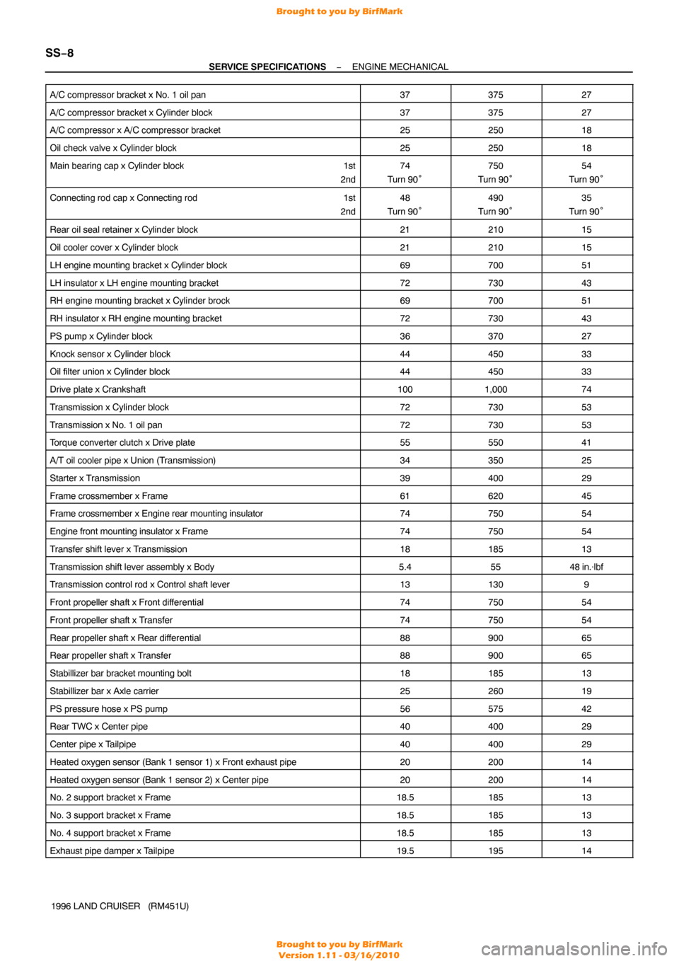
A/C compressor bracket x No. 1 oil pan
3737527
A/C compressor bracket x Cylinder block3737527
A/C compressor x A/C compressor bracket2525018
Oil check valve x Cylinder block2525018
Main bearing cap x Cylinder block
1st
2nd74
Turn 90°750
Turn 90°54
Turn 90°
Connecting rod cap x Connecting rod 1st
2nd48
Turn 90°490
Turn 90°35
Turn 90°
Rear oil seal retainer x Cylinder block2121015
Oil cooler cover x Cylinder block2121015
LH engine mounting bracket x Cylinder block6970051
LH insulator x LH engine mounting bracket7273043
RH engine mounting bracket x Cylinder brock6970051
RH insulator x RH engine mounting bracket7273043
PS pump x Cylinder block3637027
Knock sensor x Cylinder block4445033
Oil filter union x Cylinder block4445033
Drive plate x Crankshaft1001,00074
Transmission x Cylinder block7273053
Transmission x No. 1 oil pan7273053
Torque converter clutch x Drive plate5555041
A/T oil cooler pipe x Union (Transmission)3435025
Starter x Transmission3940029
Frame crossmember x Frame6162045
Frame crossmember x Engine rear mounting insulator7475054
Engine front mounting insulator x Frame7475054
Transfer shift lever x Transmission1818513
Transmission shift lever assembly x Body5.45548 in.·lbf
Transmission control rod x Control shaft lever131309
Front propeller shaft x Front dif ferential7475054
Front propeller shaft x Transfer7475054
Rear propeller shaft x Rear differential8890065
Rear propeller shaft x Transfer8890065
Stabillizer bar bracket mounting bolt1818513
Stabillizer bar x Axle carrier2526019
PS pressure hose x PS pump5657542
Rear TWC x Center pipe4040029
Center pipe x Tailpipe4040029
Heated oxygen sensor (Bank 1 sensor 1) x Front exhaust pipe2020014
Heated oxygen sensor (Bank 1 sensor 2) x Center pipe2020014
No. 2 support bracket x Frame18.518513
No. 3 support bracket x Frame18.518513
No. 4 support bracket x Frame18.518513
Exhaust pipe damper x Tailpipe19.519514
Brought to you by BirfMark
Brought to you by BirfMark
Version 1.11 - 03/16/2010