Page 1065 of 1399

Oil leak from rear dif
ferential
1. Oil level: too high or wrong grade
2. Oil seal: worn or damaged
3. C")
SA−2
−
SUSPENSION AND AXLE TROUBLESHOOTING
859
Author�: Date�:
1996 LAND CRUISER (RM451U)
Oil leak from rear dif
ferential
1. Oil level: too high or wrong grade
2. Oil seal: worn or damaged
3. Companion flange: loosen or damagedSA−73
SA−73
SA−87
Indicator lights do not light up
1. Fusible link: blown
2. GAUGE fuse: blown
3. Bulb: burned out
4. Wiring or ground: faultyBE−9
BE−9
BE−32 −
Indicator lights do not light up
(Diff. lock control switch RR or FR RR position)
1. DIFF fuse: blown
2. Diff. lock control switch: faulty
3. Diff. lock ECU: faulty
4. Wiring or ground: faultyBE−9
SA−101
SA−101 −
Differential lock does not operate
1. Diff. lock position switch: faulty
2. Diff. lock actuator: faulty
3. Diff. lock ECU: faulty
4. Differential carrier (Diff. lock): faulty
5. Wiring or ground: faultySA−101
SA−101
SA−101
SA−101−
After differential lock, lock not release
When vehicle speed is higher than approx. 8 km/h (5mph)1. Speed sensor: faulty
2. Diff. lock ECU: faulty
3. Wiring or ground: faultyBE−32
SA−101 −
Brought to you by BirfMark
Brought to you by BirfMark
Version 1.11 - 03/16/2010
Page 1076 of 1399

REMOVAL
1. REMOVE FRONT AXLE HUB (See page SA−7 )
2. REMOVE AB")
SA1UG−01
W00495
SA2644
SST
R08383
R13137
−
SUSPENSION AND AXLE STEERING KNUCKLE AND AXLE SHAFT
SA−13
1996 LAND CRUISER (RM451U)
REMOVAL
1. REMOVE FRONT AXLE HUB (See page SA−7 )
2. REMOVE ABS SPEED SENSOR
Remove the 2 bolts and disconnect the speed sensor from the
steering knuckle.
3. REMOVE DUST SEAL AND DUST COVER
Remove the 8 bolts, dust seal, dust cover and gasket.
4. REMOVE KNUCKLE SPINDLE
(a) Using a brass bar and hammer, tap the knuckle spindle of the steering knuckle.
(b) Remove the knuckle spindle and gasket.
5. REMOVE AXLE SHAFT
Position one flat part of the outer shaft upward and remove the
axle shaft.
6. DISCONNECT TIE ROD FROM KNUCKLE ARM
(a) Remove the cotter pin and nut.
(b) Using SST, disconnect the tie rod from the knuckle arm. SST 09611 −22012
7. REMOVE OIL SEAL SET
(a) Remove the 6 bolts from the end retainer.
(b) Remove these parts from the steering knuckle:
�Oil seal end retainer
�Felt dust seal
�Rubber seal
�Steel ring
8. REMOVE KNUCKLE ARM AND BEARING CAP
(a) Remove the 2 bolts and plate washers from the bearing cap.
(b) Remove the 4 nuts from the knuckle arm.
(c) Using a brass bar and hammer, tap on the 4 bolts heads and remove the 4 cone washers.
Brought to you by BirfMark
Brought to you by BirfMark
Version 1.11 - 03/16/2010
Page 1082 of 1399
−
SUSPENSION AND AXLE STEERING KNUCKLE AND AXLE SHAFT
SA−19
1996 LAND CRUISER (RM451U)
(c) Torque the 8 bolts.
Torque: 47 N·m (475 kgf·cm, 34 ft·lbf)
13. CONNECT ABS SPEED SENSOR
Connect the speed sensor and 2 bolts to the steering knuckle.
Torque: 18 N·m (185 kgf·cm, 13 ft·lbf)
14. INSTALL AXLE HUB (See page SA−9)
15. CHECK FRONT WHEEL ALIGNMENT (See page SA−4 )
16. CHECK ABS SPEED SENSOR SIGNAL (See page DI−190 )
Brought to you by BirfMark
Brought to you by BirfMark
Version 1.11 - 03/16/2010
Page 1130 of 1399
SA1V9−01
−
SUSPENSION AND AXLE REAR AXLE HUB
SA−67
1996 LAND CRUISER (RM451U)
REMOVAL
1. REMOVE REAR WHEEL
2. REMOVE REAR AXLE SHAFT (See page SA−63 )
3. REMOVE BRAKE CALIPER AND DISC (See page BR−34 )
4. DISCONNECT ABS SPEED SENSOR
Remove the bolt and disconnect the ABS speed sensor.
5. REMOVE REAR AXLE BEARING LOCK NUT
(a) Remove the 2 screws from the lock nut.
(b) Using SST, remove the lock nut. SST 09509−25011
6. REMOVE REAR AXLE HUB
(a) Pull out the axle hub, remove the lock nut plate and outer
bearing.
(b) Remove the axle hub.
Brought to you by BirfMark
Brought to you by BirfMark
Version 1.11 - 03/16/2010
Page 1131 of 1399

REPLACEMENT
1. REMOVE OIL SEAL AND INNER BEARING
(a) Using SST, rem")
SA1VA−01
R13157
Brass Bar
Positions
R13158
SST
R13159
SA−68
−
SUSPENSION AND AXLE REAR AXLE HUB
1996 LAND CRUISER (RM451U)
REPLACEMENT
1. REMOVE OIL SEAL AND INNER BEARING
(a) Using SST, remove the oil seal.
SST 09308−00010
(b) Remove the inner bearing from the hub.
2. REMOVE BEARING OUTER RACE
Using a brass bar and hammer, remove the bearing outer
races.
NOTICE:
Be careful not to damage the ABS speed sensor rotor.
3. INSTALL BEARING OUTER RACE
�Outside race:
Using SST and a press, install new bearing outer races.
SST 09950−60020 (09951 −00710),
09950 −70010 (09951 −07150)
�Inside race:
Using SST and a press, install new bearing outer races.
SST 09950−60020 (09951 −00810),
09950 −70010 (09951 −07150)
4. PACK BEARINGS WITH MP GREASE
(a) Place MP grease on the palm of your hand.
(b) Pack grease into the bearing until the grease ooze out from the other side.
(c) Do the same around the bearing circumference.
5. COAT INSIDE OF HUB WITH MP GREASE
6. INSTALL INNER BEARING AND OIL SEAL
(a) Place inner bearing into the hub.
(b) Using SST, install a new oil seal into the hub. SST 09223−15020, 09950 −70010 (09951−07150)
(c) Apply MP grease to the oil seal lip.
Brought to you by BirfMark
Brought to you by BirfMark
Version 1.11 - 03/16/2010
Page 1133 of 1399
W00498
OK
−0.2 − 0.9 mm
SA−70
−
SUSPENSION AND AXLE REAR AXLE HUB
1996 LAND CRUISER (RM451U)
(g) Check the distance between top surface of axle housing
and the lock nut.
Standard distance:
−0.2 − 0.9 mm (−0.0079 − 0.0354 in.)
If the distance is greater than the specification, reassemble the
lock nut plate.
(h) Check that the hub with disc rotates smoothly and hub has no axial play.
5. INSTALL BEARING LOCK NUT SCREW
Tighten the 2 lock nut screws. Torque: 5.4 N·m (55 kgf·cm, 48 in.·lbf)
6. CONNECT ABS SPEED SENSOR
Connect the ABS speed sensor install the bolt.
Torque: 18 N·m (185 kgf·cm, 13 ft·lbf)
7. INSTALL BRAKE CALIPER (See page BR−38 )
8. INSTALL REAR AXLE SHAFT (See page SA−65 )
9. INSTALL REAR WHEEL Torque:
Steel wheel: 147 N·m (1,500 kgf·cm, 109 ft·lbf)
Aluminum wheel: 103 N·m (1,050 kgf·cm, 76 ft·lbf)
10. CHECK ABS SPEED SENSOR SIGNAL (See page DI−190 )
Brought to you by BirfMark
Brought to you by BirfMark
Version 1.11 - 03/16/2010
Page 1134 of 1399
SA1VC−01
−
SUSPENSION AND AXLE REAR WHEEL HUB BOLT
SA−71
928
Author�: Date�:
1996 LAND CRUISER (RM451U)
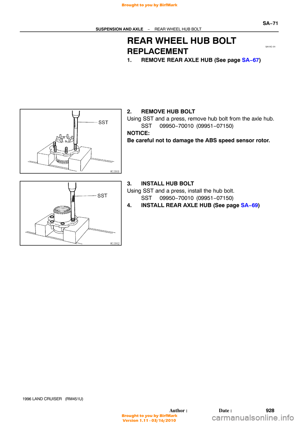
REAR WHEEL HUB BOLT
REPLACEMENT
1. REMOVE REAR AXLE HUB (See page SA−67 )
2. REMOVE HUB BOLT
Using SST and a press, remove hub bolt from the axle hub. SST 09950−70010 (09951 −07150)
NOTICE:
Be careful not to damage the ABS speed sensor rotor.
3. INSTALL HUB BOLT
Using SST and a press, install the hub bolt. SST 09950−70010 (09951 −07150)
4. INSTALL REAR AXLE HUB (See page SA−69 )
Brought to you by BirfMark
Brought to you by BirfMark
Version 1.11 - 03/16/2010
Page 1165 of 1399

(6) Check the voltage between the terminals")
Z07254
M3 M4 M1 M2
Z07255
Wire Harness Side
SA−102
−
SUSPENSION AND AXLE DIFFERENTIAL LOCKING SYSTEM
959
Author�: Date�:
1996 LAND CRUISER (RM451U)
(6) Check the voltage between the terminals of the Diff.
lock ECU when switching the Diff. lock control
switch with the speedometer, registering approx. 8
km/h (5 mph) or more.
(7) Check that the indicator lights blink when center Diff. lock release mode is set.
Diff. lock is released for both the front wheels and
rear wheels at this time.
(8) Return the Diff. lock control switch to OFF.
(9) Stop the engine and lower the vehicle.
2. INSPECT DIFF. LOCK SYSTEM CIRCUIT
(a) Inspect the system circuit with connector disconnected. Disconnect the connector from the Diff. lock ECU and in-
spect the connector on the wire harness side, as shown
in the chart.
Trouble Part/
Terminals (Symbols)ConditionSpecified V alue
Rear diff. lock actuator/
1 (M2) − 3 (M1)−Less than 100 Ω
Front diff. lock actuator/
5 (M4) − 7 (M1)−Less than 100 Ω
Body ground/
13 (GND) − Body ground−Continuity
Vehicle speed sensor/
4(SPD) − Body groundVehicle moving slowly1 pulse each 40 cm (15.75 in.)
Brought to you by BirfMark
Brought to you by BirfMark
Version 1.11 - 03/16/2010

(c) Torque the 8 bolts.
Torque: 47 N·m (475 kgf·cm, 34 ft·lbf)
13. CONNECT ABS SPEED SENSOR
Connect the")

REMOVAL
1. REMOVE REAR WHEEL
2. REMOVE REAR AXLE SHAFT (See page SA−63 )
3. REMOVE BRAKE CALIPER AND DISC (See")

(g) Check the distance between top surface of axle housing
and the lock nut.
Standard distance")