Page 44 of 1399
AC−2
−
AIR CONDITIONING AIR CONDITIONING SYSTEM
1329
Author�: Date�:
1996 LAND CRUISER (RM451U)
9. SUPPLEMENTAL RESTRAINT SYSTEM (SRS)
The LAND CRUISER is equipped with an SRS (Spplemental
Restraint System)such as the driver airbag and passenger air
bag. Failure to carry out service operations in the correct se-
quence could cause the SRS to unexpectedly deployed during
servicing, possibly leading to a serious accident. Further, if a
mistake is made in servicing the SRS, it is possible the SRS may
fail to operate when required. Before servicing (including re-
moval or installation of parts, inspection or replacement), be
sure to read the following item carefully, then follow the correct
procedure described in the repair manual.
Brought to you by BirfMark
Brought to you by BirfMark
Version 1.11 - 03/16/2010
Page 53 of 1399

N13795
Quick Disconnect
AdapterCharging
Service Valve Hose
AC2QE−01
N13794
Vacuum Pump
Vacuum Pump Adapter
N13791
Low Pressure
Service Valve
Vacuum Pump Adapter
High Pressure
Service Valve Manifold
Gauge
Set
−
AIR CONDITIONING AIR CONDITIONING SYSTEM
AC−11
1996 LAND CRUISER (RM451U)
EVACUATING
1. CONNECT QUICK DISCONNECT ADAPTERS TO
CHARGING HOSES
2. REMOVE CAPS FROM SERVICE VALVES ON RE- FRIGERANT LINES
3. INSTALL MANIFOLD GAUGE SET
(a) Close both hand valves of manifold gauge set.
(b) Connect the quick disconnect adapters to the service valves.
4. EVACUATE AIR FROM REFRIGERATION SYSTEM
(a) Connect the vacuum pump adapter to the vacuum pump.
(b) Connect the center hose of the manifold gauge set to the vacuum pump adapter.
(c) Open both the high and low hand valves and run the vacu-
um pump.
(d) After 10 minutes or more, check that the low pressure
gauge indicates 750 mmHg (30 in.Hg) or more.
HINT:
If the reading is not 750 mmHg (30 in.Hg) or more, close both
hand valves of manifold gauge set and stop the vacuum pump.
Check the system for leaks and repair as necessary.
(e) Close both the high and low hand valves and stop the vac-
uum pump.
(f) Leave the system in this condition for 5 minutes or more and check that there is no gauge indicator.
Brought to you by BirfMark
Brought to you by BirfMark
Version 1.11 - 03/16/2010
Page 54 of 1399

CHARGING
1. INSTALL")
AC2QF−01
N13790
Low Pressure
Service ValveHigh Pressure
Service Valve
N13792
Gas Leak Detector
AC−12
−
AIR CONDITIONING AIR CONDITIONING SYSTEM
1996 LAND CRUISER (RM451U)
CHARGING
1. INSTALL CHARGING CYLINDER
HINT:
When handling the charging cylinder, always follow the direc-
tion given in the instruction manual.
(a) Charge the proper amount of refrigerant in charging cylin-
der.
(b) Connect the center hose to the charging cylinder.
CAUTION:
Do not open both high and low hand valves of manifold
gauge set.
(c) Open the valve of charging cylinder.
(d) Press the valve core on the side of manifold gauge and expel the air inside of the center hose.
2. INSPECT REFRIGERATION SYSTEM FOR LEAKS
(a) Open the high pressure hand valve and charge refriger- ant.
(b) When the low pressure gauge indicates 98 kPa (1 kgf/cm
2, 14 psi), close the high pressure hand valve.
(c) Using leak detector, check the system for leakage.
(d) If leak is found, repair the faulty component or connection. Add evacuate air from refrigeration system (Refer to 4).
CAUTION:
Use the refrigerant recovery/ recycling machine to recover
the refrigerant whenever replacing parts.
Brought to you by BirfMark
Brought to you by BirfMark
Version 1.11 - 03/16/2010
Page 56 of 1399
−
AIR CONDITIONING AIR CONDITIONING SYSTEM
AC−13
1996 LAND CRUISER (RM451U)
3. CHARGE REFRIGERANT INTO REFRIGERANT SYS-
TEM
If there is no leak after refrigerant leak check charge, the proper
amount of refrigerant into refrigeration system.
CAUTION:
Never run the engine when charging the system through
the high pressure side.Do not open the low pressure hand
valve when the system is being charged with liquid refrig-
erant.
(a) Open the high pressure hand valve fully.
(b) Charge specified amount of refrigerant, then close the high pressure hand valve.
HINT:
A fully charged system is indicated by the sight glass being free
of any bubbles.
4. REMOVE MANIFOLD GAUGE SET
(a) Close both hand valves of manifold gauge set.
(b) Disconnect the quick disconnect adapters from the ser- vice valves.
5. INSTALL CAPS TO SERVICE VALVES ON REFRIGER-
ANT LINES
Brought to you by BirfMark
Brought to you by BirfMark
Version 1.11 - 03/16/2010
Page 61 of 1399
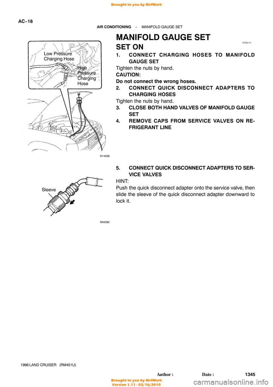
N14326
Low Pressure
Charging Hose
High
Pressure
Charging
Hose
AC2QJ−01
N04392
Sleeve
AC−18
−
AIR CONDITIONING MANIFOLD GAUGE SET
1345
Author�: Date�:
1996 LAND CRUISER (RM451U)
MANIFOLD GAUGE SET
SET ON
1. CONNECT CHARGING HOSES TO MANIFOLD
GAUGE SET
Tighten the nuts by hand.
CAUTION:
Do not connect the wrong hoses.
2. CONNECT QUICK DISCONNECT ADAPTERS TO CHARGING HOSES
Tighten the nuts by hand.
3. CLOSE BOTH HAND VALVES OF MANIFOLD GAUGE
SET
4. REMOVE CAPS FROM SERVICE VALVES ON RE- FRIGERANT LINE
5. CONNECT QUICK DISCONNECT ADAPTERS TO SER-
VICE VALVES
HINT:
Push the quick disconnect adapter onto the service valve, then
slide the sleeve of the quick disconnect adapter downward to
lock it.
Brought to you by BirfMark
Brought to you by BirfMark
Version 1.11 - 03/16/2010
Page 62 of 1399
AC2QK−01
N06553
−
AIR CONDITIONING MANIFOLD GAUGE SET
AC−19
1996 LAND CRUISER (RM451U)
SET OFF
1. CLOSE BOTH HAND VALVES OF MANIFOLD GAUGE
SET
2. DISCONNECT QUICK DISCONNECT ADAPTERS FROM SERVICE VALVES ON REFRIGERANT LINE
HINT:
Slide the sleeve of the quick disconnect adapter upward to un-
lock the adapter and remove it from the service valve.
3. INSTALL CAPS TO SERVICE VALVES ON REFRIGER-
ANT LINE
t
=
QJL
Brought to you by BirfMark
Brought to you by BirfMark
Version 1.11 - 03/16/2010
Page 145 of 1399

BODY ELECTRICAL SYSTEM
PRECAUTION
Take care to observe the following precautions when per")
BE1LS−01
−
BODY ELECTRICAL BODY ELECTRICAL SYSTEM
BE−1
1139
Author�: Date�:
1996 LAND CRUISER (RM451U)
BODY ELECTRICAL SYSTEM
PRECAUTION
Take care to observe the following precautions when performing inspections o\
r removal and replacement
of body electrical related parts.
1. HEADLIGHT SYSTEM
Halogen bulbs have pressurized gas inside and require special handling. They ca\
n burst if scratched or
dropped. Hold a bulb only by its plastic or metal case. Don’t touch the glass\
part of a bulb with bare hands.
2. SRS (SUPPLEMENTAL RESTRAINT SYSTEM)
The LAND CRUISER is equipped with an SRS (Supplemental Restraint System) such as the driver airbag
and front passenger airbag. Failure to carry out service operation in th\
e correct sequence could cause the
SRS to unexpectedly deploy during servicing, possibly leading to a serious accident. Before servicing (in\
-
cluding removal or installation of parts, inspection or replacement), be sure t\
o read the precautionary notices
in the RS section.
3. AUDIO SYSTEM
If the negative (−) terminal cable is disconnected from the battery, the preset AM, FM 1 and FM 2 stations
stored in memory are erased, so be sure to note the stations and reset them af\
ter the negative ( −) terminal
cable is reconnected to the battery.
4. MOBILE COMMUNICATION SYSTEM
If the vehicle is equipped with a mobile communication system, refer to \
precautions in the IN section.
Brought to you by BirfMark
Brought to you by BirfMark
Version 1.11 - 03/16/2010
Page 214 of 1399

FM (Monaural) AM
BE2819
Fadinglo")
BE0SA−01
30 kHz300 kHz 3 MHz 30 MHz300 MHz
LF MF HFVHF
AM FM
Frequency modulation
Frequency
Designation
Radio wave
Modulation
Amplitube modulation
BE2818
FM (Stereo)
FM (Monaural) AM
BE2819
Fadinglonosphere
BE−70
−
BODY ELECTRICAL AUDIO SYSTEM
1208
Author�: Date�:
1996 LAND CRUISER (RM451U)
AUDIO SYSTEM
DESCRIPTION
1. RADIO WAVE BAND
The radio wave bands used in radio broadcasting are as follows:
LF: Low Frequency
MF: Medium Frequency
HF: High Frequency
VHF: Very High Frequency
2. SERVICE AREA
There are great dif ferences in the size of the service area for AM
and FM monaural. Sometimes FM stereo broadcasts cannot be
received even through AM can be received in very clearly.
Not only does FM stereo have the smallest service area, but it
also picks up static and other types of interference (”noise”)
easily.
3. RECEPTION PROBLEMS
Besides the problem of static, there are also the problems
called ”fading”, ”multipath” and ”fade out”. These problems \
are
caused not by electrical noise but by the nature of the radio
waves themselves.
(1) FadingBesides electrical interference, AM broadcasts are
also susceptible to other types of interference, es-
pecially at night. This is because AM radio waves
bounce off the ionosphere at night. These radio
waves then interfere with the signals from the same
transmitter that reach the vehicle’ s antenna directly.
This type of interference is called ”fading”.
Brought to you by BirfMark
Brought to you by BirfMark
Version 1.11 - 03/16/2010


3. CHARGE REFRIGERANT INTO REFRIGERANT SYS-
TEM
If there is no leak after refrigerant leak check charge, the proper
a")

SET OFF
1. CLOSE BOTH HAND VALVES OF MANIFOLD GAUGE
SET
2. DISCONNECT QUICK DISCONNECT ADAPTERS FROM SERV")