Page 49 of 1399

I01389
Condition: Insufficient cooling
I01449
Condition: Does not cool (Cools from time to time in some cases)
−
AIR CONDITIONING AIR CONDITIONING SYSTEM
AC−7
1996 LAND CRUISER (RM451U)
(4) Poor circulation of refrigerant
Symptom seen in
refrigeration systemProbable causeDiagnosisRemedy
� Pressure low in both low and
high pressure sides
� Frost on tube from condenser to
unit
Refrigerant flow obstructed by dirt
in condensercondenser cloggedReplace condenser
(5) Refrigerant does not circulate
Symptom seen in
refrigeration systemProbable causeDiagnosisRemedy
� Vacuum indicated on low pres-
sure side, very low pressure indi-
cated on high pressure side
� Frost or dew seen on piping be-
fore and after condenser/ drier or
expansion valve� Refrigerant flow obstructed by
moisture or dirt in refrigeration sys-
tem
� Refrigerant flow obstructed by
gas leakage from expansion valve
Refrigerant does not circulate
(1) Check expansion valve
(2) Clean out dirt in expansion
valve by blowing with air
(3) Replace condenser
(4) Evacuate air and charge new
refrigerant to proper amount
(5) For gas leakage from expan-
sion valve, replace expansion
valve
Brought to you by BirfMark
Brought to you by BirfMark
Version 1.11 - 03/16/2010
Page 50 of 1399

I01390
Condition: Insufficient cooling
I01392
Condition: Insufficient coolingNOTE : These gauge indica-
tions are shown when the
refrigeration system has
been opened and the refrig-
erant charged without vacu-
um purging.
AC−8
−
AIR CONDITIONING AIR CONDITIONING SYSTEM
1996 LAND CRUISER (RM451U)
(6) Refrigerant overcharged or insufficient cooling of
condenser
Symptom seen in
refrigeration systemProbable causeDiagnosisRemedy
� Pressure too high on both low
and high pressure sides
� No air bubbles seen through the
sight glass even when the engine
rpm is lowered� Unable to develop sufficient per-
formance due to excessive refrig-
eration system
� Insufficient cooling of condenser� Excessive refrigerant in
cycle → refrigerant over charged
� Condenser cooling → condenser
fins clogged or cooling fan faulty
(1) Clean condenser
(2) Check cooling fan with fluid
coupling operation
(3) If (1) and (2) are in normal
state, check amount of refrigerant
Charge proper amount of refriger-
ant
(7) Air present in refrigeration system
Symptom seen in
refrigeration systemProbable causeDiagnosisRemedy
� Pressure too high on both low
and high pressure sides
� The low pressure piping hot to
touch
� Bubbles seen in sight glass
Air entered in refrigeration system
� Air present in refrigeration sys-
tem
� Insufficient vacuum purging
(1) Check compressor oil to see if
it is dirty or insuf ficient
(2) Evacuate air and charge new
refrigerant
Brought to you by BirfMark
Brought to you by BirfMark
Version 1.11 - 03/16/2010
Page 53 of 1399

N13795
Quick Disconnect
AdapterCharging
Service Valve Hose
AC2QE−01
N13794
Vacuum Pump
Vacuum Pump Adapter
N13791
Low Pressure
Service Valve
Vacuum Pump Adapter
High Pressure
Service Valve Manifold
Gauge
Set
−
AIR CONDITIONING AIR CONDITIONING SYSTEM
AC−11
1996 LAND CRUISER (RM451U)
EVACUATING
1. CONNECT QUICK DISCONNECT ADAPTERS TO
CHARGING HOSES
2. REMOVE CAPS FROM SERVICE VALVES ON RE- FRIGERANT LINES
3. INSTALL MANIFOLD GAUGE SET
(a) Close both hand valves of manifold gauge set.
(b) Connect the quick disconnect adapters to the service valves.
4. EVACUATE AIR FROM REFRIGERATION SYSTEM
(a) Connect the vacuum pump adapter to the vacuum pump.
(b) Connect the center hose of the manifold gauge set to the vacuum pump adapter.
(c) Open both the high and low hand valves and run the vacu-
um pump.
(d) After 10 minutes or more, check that the low pressure
gauge indicates 750 mmHg (30 in.Hg) or more.
HINT:
If the reading is not 750 mmHg (30 in.Hg) or more, close both
hand valves of manifold gauge set and stop the vacuum pump.
Check the system for leaks and repair as necessary.
(e) Close both the high and low hand valves and stop the vac-
uum pump.
(f) Leave the system in this condition for 5 minutes or more and check that there is no gauge indicator.
Brought to you by BirfMark
Brought to you by BirfMark
Version 1.11 - 03/16/2010
Page 335 of 1399

BR1CD−01
BR−2
−
BRAKE TROUBLESHOOTING
984
Author�: Date�:
1996 LAND CRUISER (RM451U)
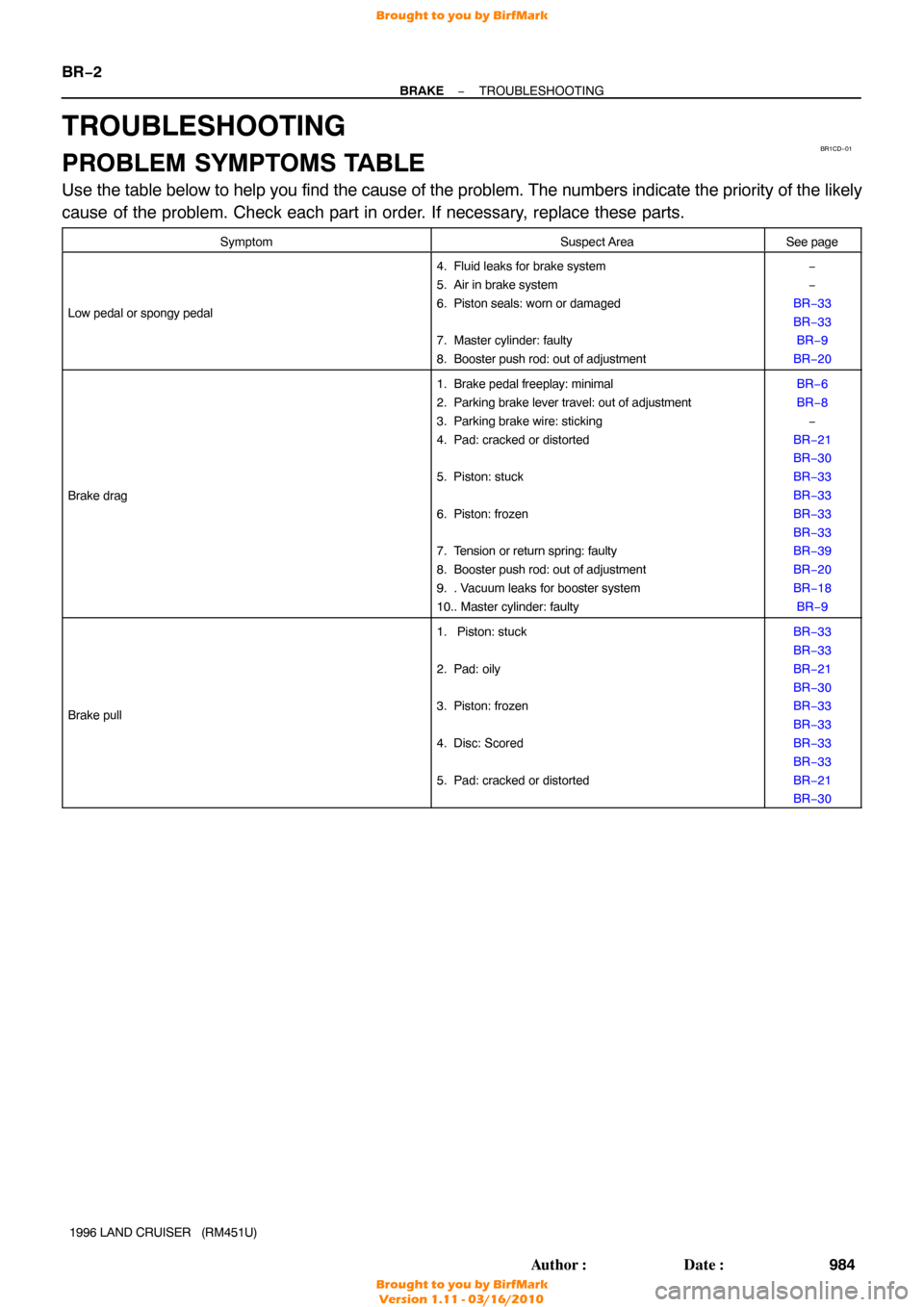
TROUBLESHOOTING
PROBLEM SYMPTOMS TABLE
Use the table below to help you find the cause of the problem. The numbers \
indicate the priority of the likely
cause of the problem. Check each part in order. If necessary, replace these parts.
SymptomSuspect AreaSee page
Low pedal or spongy pedal
4. Fluid leaks for brake system
5. Air in brake system
6. Piston seals: worn or damaged
7. Master cylinder: faulty
8. Booster push rod: out of adjustment−
−
BR−33
BR−33 BR−9
BR−20
Brake drag
1. Brake pedal freeplay: minimal
2. Parking brake lever travel: out of adjustment
3. Parking brake wire: sticking
4. Pad: cracked or distorted
5. Piston: stuck
6. Piston: frozen
7. Tension or return spring: faulty
8. Booster push rod: out of adjustment
9. . Vacuum leaks for booster system
10.. Master cylinder: faultyBR−6
BR−8 −
BR−21
BR−30
BR−33
BR−33
BR−33
BR−33
BR−39
BR−20
BR−18 BR−9
Brake pull
1. Piston: stuck
2. Pad: oily
3. Piston: frozen
4. Disc: Scored
5. Pad: cracked or distortedBR−33
BR−33
BR−21
BR−30
BR−33
BR−33
BR−33
BR−33
BR−21
BR−30
Brought to you by BirfMark
Brought to you by BirfMark
Version 1.11 - 03/16/2010
Page 336 of 1399
−
BRAKE TROUBLESHOOTING
BR−3
985
Author�: Date�:
1996 LAND CRUISER (RM451U)
Hard pedal but brake inef
ficient
1. Fluid leaks for brake system
2. Air in brake system
3. Pad: worn
4. Pad: cracked or distorted
5. Pad: oily
6. Pad: glazed
7. Disc: scored
8. Booster push rod: out of adjustment
9. Vacuum leaks for booster system−
−
BR−21
BR−30
BR−21
BR−30
BR−21
BR−30
BR−21
BR−30
BR−21
BR−30
BR−20
BR−18
Noise from brake
1. Pad: cracked or distorted
2. Installation bolt: loosen
3. Disc: scored
4. Pad support plate: loosen
5. Sliding pin: worn
6. Pad: dirty
7. Pad: glazed
8. Tension or return spring: faulty
9. Anti− squeal shim: damaged
10.. Hold− down spring: damagedBR−21
BR−30
BR−33
BR−33
BR−33
BR−33
BR−30
BR−33
BR−21
BR−30
BR−21
BR−30
BR−39
BR−21
BR−30
BR−39
Brought to you by BirfMark
Brought to you by BirfMark
Version 1.11 - 03/16/2010
Page 339 of 1399

BR3295
Push RodStop Light Switch
Pedal Height
BR1CF−04
BR4980
A
BR0016
Pedal Freeplay
BR−6
−
BRAKE BRAKE PEDAL
988
Author�: Date�:
1996 LAND CRUISER (RM451U)
BRAKE PEDAL
ON−VEHICLE INSPECTION
1. CHECK PEDAL HEIGHT
Pedal height from dash panel:
167.5 − 177.5 mm (6.594 − 6.988 in.)
2. IF NECESSARY, ADJUST PEDAL HEIGHT
(a) Disconnect the connector from the stop light switch.
(b) Loosen the stop light switch lock nut and remove the stop
light switch.
(c) Loosen the push rod lock nut.
(d) Adjust the pedal height by turning the pedal push rod.
(e) Tighten the push rod lock nut. Torque: 25 N·m (260 kgf·cm, 19 ft·lbf)
(f) Install the stop light switch and turn it until it lightly con-
tacts the pedal stopper.
(g) Turn the stop light switch back one turn.
(h) Check the clearance (A) between the stop light switch and pedal.
Clearance: 0.5 − 2.4 mm (0.020 − 0.094 in.)
(i) Tighten the stop light switch lock nut.
(j) Connect the connector to the stop light switch.
(k) Check that the stop lights come on when the brake pedal
is depressed, and go off when the brake pedal is re-
leased.
(l) earance (A) between the stop light switch and the pedal
stopper has been adjusted correctly, the pedal freeplay
will meet the specifications.
3. CHECK PEDAL FREEPLAY
(a) Stop the engine and depress the brake pedal several times until there is no more vacuum left in the booster.
(b) Push in the pedal by hand until the beginning of the se- cond resistance is felt. Measure the distance.
Pedal freeplay: 3 − 6 mm (0.12 − 0.24 in.)
HINT:
The freeplay to the 1st resistance is due to the play between the
clevis and pin. This is magnified up to 3 − 6 mm (0.12 − 0.24 in.)
at the pedal.
Brought to you by BirfMark
Brought to you by BirfMark
Version 1.11 - 03/16/2010
Page 352 of 1399
BR1CP−03
BR3753
−
BRAKE BRAKE BOOSTER ASSEMBLY
BR−19
1996 LAND CRUISER (RM451U)
REMOVAL
1. REMOVE MASTER CYLINDER (See page BR−9 )
2. REMOVE THESE PARTS:
�Return spring
�Clip and clevis pin
�Clevis
�Vacuum hose
3. REMOVE BRAKE BOOSTER
(a) Remove the 4 booster installation nuts.
(b) Remove the booster and gasket.
Brought to you by BirfMark
Brought to you by BirfMark
Version 1.11 - 03/16/2010
Page 353 of 1399

BR1CQ−01
BR3976
SST
Gasket
R11347
SST
BR−20
−
BRAKE BRAKE BOOSTER ASSEMBLY
1996 LAND CRUISER (RM451U)
INSTALLATION
1. INSTALL BRAKE BOOSTER
(a) Install the booster and a new gasket.
(b) Install the clevis to the operating rod.
(c) Install and torque the booster installation nuts. Torque: 13 N·m (130 kgf·cm, 9 ft·lbf)
(d) Install the clevis pin into the clevis and brake pedal, and
install the clip to the clevis pin.
(e) Install the pedal return spring.
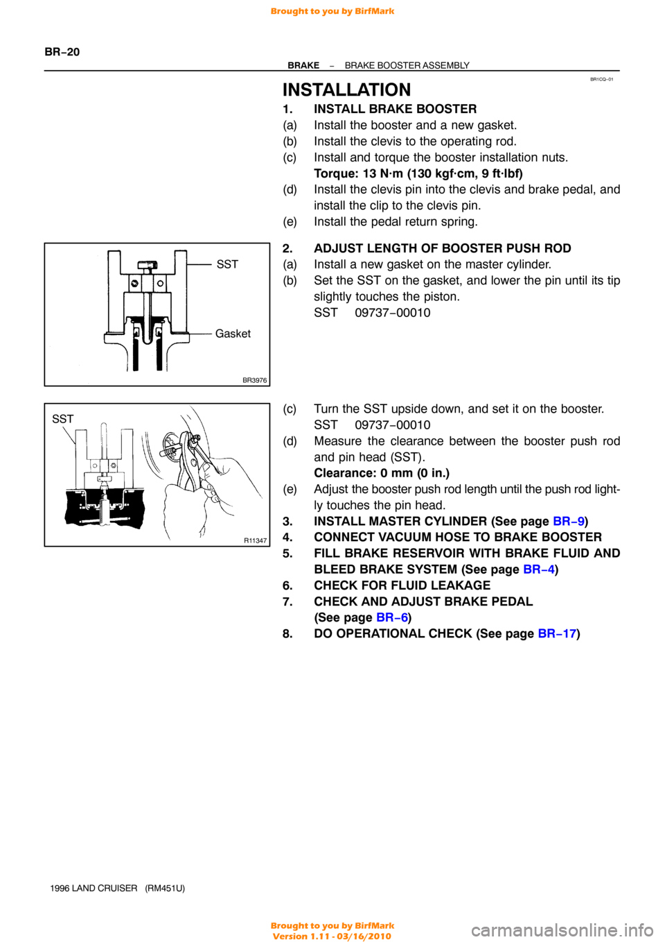
2. ADJUST LENGTH OF BOOSTER PUSH ROD
(a) Install a new gasket on the master cylinder.
(b) Set the SST on the gasket, and lower the pin until its tip slightly touches the piston.
SST 09737−00010
(c) Turn the SST upside down, and set it on the booster. SST 09737−00010
(d) Measure the clearance between the booster push rod and pin head (SST).
Clearance: 0 mm (0 in.)
(e) Adjust the booster push rod length until the push rod light-
ly touches the pin head.
3. INSTALL MASTER CYLINDER (See page BR−9 )
4. CONNECT VACUUM HOSE TO BRAKE BOOSTER
5. FILL BRAKE RESERVOIR WITH BRAKE FLUID AND
BLEED BRAKE SYSTEM (See page BR−4 )
6. CHECK FOR FLUID LEAKAGE
7. CHECK AND ADJUST BRAKE PEDAL (See page BR−6 )
8. DO OPERATIONAL CHECK (See page BR−17 )
Brought to you by BirfMark
Brought to you by BirfMark
Version 1.11 - 03/16/2010