1996 TOYOTA LAND CRUISER Engine oil level
[x] Cancel search: Engine oil levelPage 552 of 1399

P22480
BatteryStarter
FL MAIN
FL AM2EFI
EFI Main Relay
IG Switch IG
ST
Park/Neutral
Position SwitchCircuit Opening
Relay
Fuel Pump Relay
Fuel Pump
From Crankshaft Position
Sensor Fuel Pump
Resistor
(STA Signal)
(NE Signal) MRLY
FC
STA
NE
Tr1
Tr2
ECM
IGN FPR
−
DIAGNOSTICS ENGINE
DI−11 5
1996 LAND CRUISER (RM451U)
Fuel Pump Control Circuit
CIRCUIT DESCRIPTION
In the diagram below, when the engine is cranked, current flows form terminal ST of the igni\
tion switch to
terminal STA of ECM (STA signal).
When the STA signal and NE signal are input to the ECM, Tr1 is turned ON, current flows to coil of the circuit
opening relay, the relay switches on, power is supplied to the fuel pump and the fuel\
pump operates.
While the NE signal is generated (engine running), the ECM keeps Tr1 ON (circuit opening relay ON) and
the fuel pump also keeps operating.
The fuel pump speed is controlled at 2 levels (high speed or low speed) b\
y the condition of the engine (start-
ing, light load, heavy load). When the engine starts (STA ON), Tr2 in the ECM is OFF, so battery voltage is
applied directry to the fuel pump. Fuel pump operates at high speed.
After the engine starts, during idling or light loads, since Tr2 goes ON, power is supplied to the fuel pump
via the fuel pump resistor.
Fuel pump operates at low speed.
DI5PY−02
Brought to you by BirfMark
Brought to you by BirfMark
Version 1.11 - 03/16/2010
Page 575 of 1399

Q07308
AT3417
OK if hot
Add if hot
AT4252
0 − 1 mm
Q07309
DI−138
−
DIAGNOSTICS AUTOMATIC TRANSMISSION
1996 LAND CRUISER (RM451U)
(3) With the engine OFF, add new fluid through the oil
filler pipe.
Fluid type: ATF DEXRON ®II
Capacity:
Dry fill: 11.0 liters (11.6 US qts, 9.7 Imp. qts)
Drain and refill: 1.9 liters (2.0 US qts, 1.7 Imp. qts)
(4) Start the engine and shift the shift lever into all posi-
tions from P to L position and then shift into P posi-
tion.
(5) With the engine idling, check the fluid level. Add fluid up to the COOL level on the dipstick.
(6) Check the fluid level at the normal operating tem- perature 70 − 80° C (158 − 176°F) and add as nec-
essary.
NOTICE:
Do not overfill.
(d) Check the fluid leaks.
Check for leaks in the transmission.
If there are leaks, it is necessary to repair or replace O −rings,
Seal packings, oil seals, plugs or other parts.
(e) Inspect and adjust the throttle cable. (1) Check that the throttle valve is fully closed.
(2) Check that the inner cable is not slack.
(3) Measure the distance between the outer cable endand stopper on the cable.
Standard distance: 0 − 1 mm (0 − 0.04 in.)
If the distance is not standard, adjust the cable by the adjusting
nuts.
(f) Inspect and adjust the shift lever position. When shifting the shift lever from the N position to other
positions, check that the lever can be shifted smoothly
and accurately to each position and that the position indi-
cator correctly indicates the position.
If the indicator is not aligned with the correct position, carry out
the following adjustment procedures. (1) Loosen the nut on the control rod.
(2) Push the control rod fully rearward.
Brought to you by BirfMark
Brought to you by BirfMark
Version 1.11 - 03/16/2010
Page 799 of 1399

EM−14
−
ENGINE MECHANICAL TIMING CHAIN
1996 LAND CRUISER (RM451U)
9. DISCONNECT OIL COOLER PIPE BRACKET FROM
NO. 1 OIL PAN
10. REMOVE OIL LEVEL SENSOR
(a) Remove the 4 bolts and level sensor.
(b) Remove the gasket from the level sensor.
11. REMOVE BOLTS HOLDING NO.1 OIL PAN TO TRANS-
MISSION HOUSING
Remove the 6 bolts.
12. REMOVE NO. 2 OIL PAN (See page LU−5)
13. REMOVE NO. 1 OIL PAN (See page LU−5)
14. REMOVE CRANKSHAFT PULLEY
(a) Using SST, remove the pulley bolt. SST 09213−58012, 09330 −00021
(b) Remove the crankshaft pulley.
HINT:
If necessary, remove the pulley with SST. SST 09950−50010 (09951 −05010, 09952−05010,
09953 −05010, 09953 −05020, 09954−05020)
Brought to you by BirfMark
Brought to you by BirfMark
Version 1.11 - 03/16/2010
Page 808 of 1399

−
ENGINE MECHANICAL TIMING CHAIN
EM−23
1996 LAND CRUISER (RM451U)
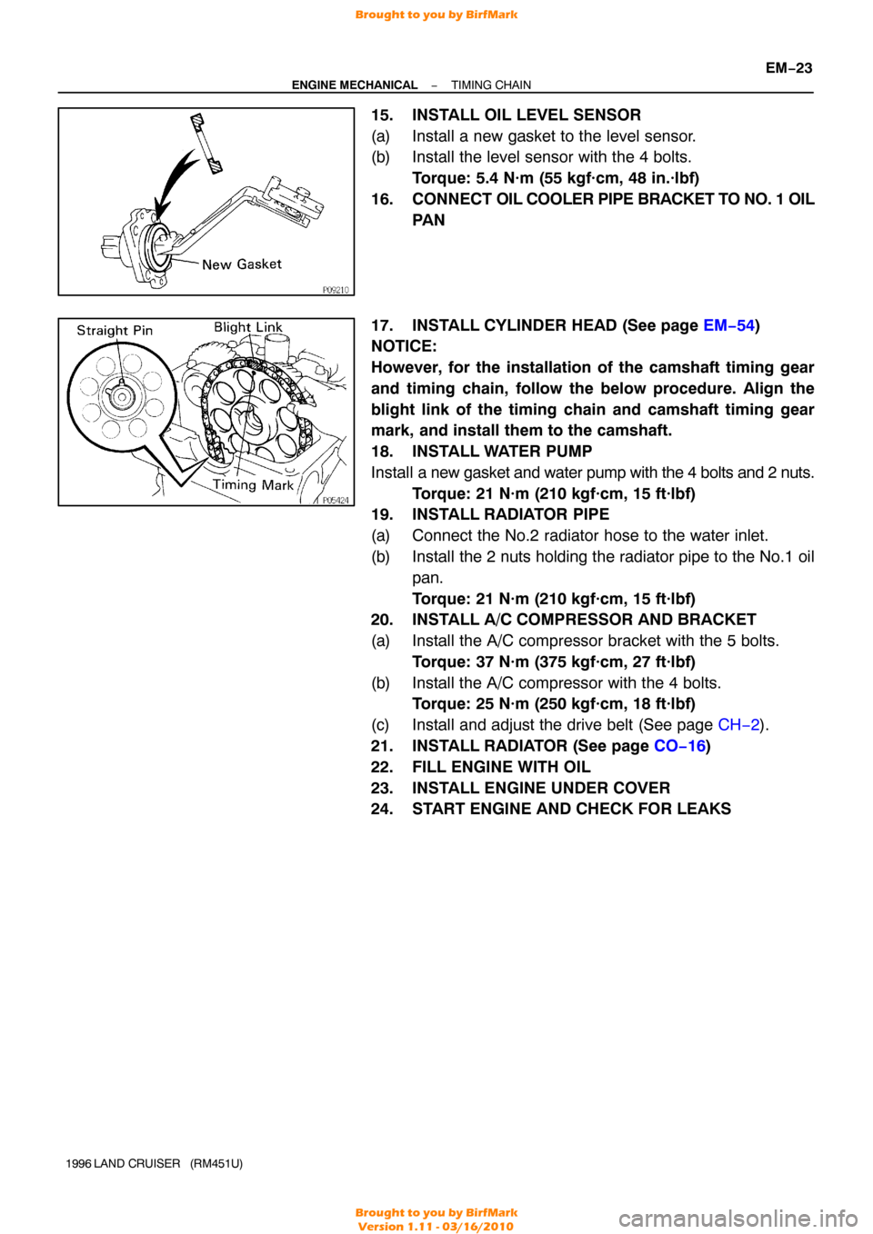
15. INSTALL OIL LEVEL SENSOR
(a) Install a new gasket to the level sensor.
(b) Install the level sensor with the 4 bolts.
Torque: 5.4 N·m (55 kgf·cm, 48 in.·lbf)
16. CONNECT OIL COOLER PIPE BRACKET TO NO. 1 OIL
PA N
17. INSTALL CYLINDER HEAD (See page EM−54 )
NOTICE:
However, for the installation of the camshaft timing gear
and timing chain, follow the below procedure. Align the
blight link of the timing chain and camshaft timing gear
mark, and install them to the camshaft.
18. INSTALL WATER PUMP
Install a new gasket and water pump with the 4 bolts and 2 nuts.
Torque: 21 N·m (210 kgf·cm, 15 ft·lbf)
19. INSTALL RADIATOR PIPE
(a) Connect the No.2 radiator hose to the water inlet.
(b) Install the 2 nuts holding the radiator pipe to the No.1 oil
pan.
Torque: 21 N·m (210 kgf·cm, 15 ft·lbf)
20. INSTALL A/C COMPRESSOR AND BRACKET
(a) Install the A/C compressor bracket with the 5 bolts.
Torque: 37 N·m (375 kgf·cm, 27 ft·lbf)
(b) Install the A/C compressor with the 4 bolts. Torque: 25 N·m (250 kgf·cm, 18 ft·lbf)
(c) Install and adjust the drive belt (See page CH−2).
21. INSTALL RADIATOR (See page CO−16 )
22. FILL ENGINE WITH OIL
23. INSTALL ENGINE UNDER COVER
24. START ENGINE AND CHECK FOR LEAKS
Brought to you by BirfMark
Brought to you by BirfMark
Version 1.11 - 03/16/2010
Page 815 of 1399

EM−30
−
ENGINE MECHANICAL CYLINDER HEAD
1996 LAND CRUISER (RM451U)
(b) Disconnect the connectors.
(1) Disconnect the knock sensor connector.
(2) Disconnect the oil level sensor connector.
(3) Disconnect the 2 connectors from the transmission.
(4) Disconnect the starter connector.
(c) Disconnect the 2 heated oxygen sensor connectors.
(d) Disconnect the PNP switch connector.
(e) Remove the 2 bolts and disconnect the engine wire from the intake manifold and cylinder block.
(f) Disconnect the PCV hose from the PCV valve.
(g) Remove the bolt holding the engine wire to the intake manifold.
(h) Disconnect the connectors. (1) Disconnect the connector for the emission controlvalve set assembly.
(2) Disconnect the 3 injector connectors.
(i) Disconnect the engine wire clamp.
(j) Disconnect the engine wire clamp.
(k) Disconnect the connectors.
(1) Disconnect the 3 injector connectors.
(2) Disconnect the EGR gas temp. sensor connector.
(l) Disconnect the clamp of the No. 6 injector wire from the bracket.
(m) Disconnect the engine wire from the cylinder head and in-
take manifold.
25. DISCONNECT NO. 2 WATER BYPASS PIPE
Remove the 3 bolts, and disconnect the bypass pipe from the
cylinder head.
Brought to you by BirfMark
Brought to you by BirfMark
Version 1.11 - 03/16/2010
Page 847 of 1399

EM−62
−
ENGINE MECHANICAL CYLINDER HEAD
1996 LAND CRUISER (RM451U)
(h) Connect the engine wire to the intake manifold and cylin-
der block with the 2 bolts.
(i) Connect the PNP switch connector.
(j) Connect the 2 heated oxygen sensor connectors.
(k) Connect the connectors.
(1) Connect the Knock sensor connector.
(2) Connect the oil level sensor connector.
(3) Connect the 2 connectors to tthe ransmission.
(4) Connect the starter connector.
(l) Connect the engine wire to the cylinder block with the bolt.
(m) Connect the connectors.
(1) Connect the ECT sender gauge connector.
(2) Connect the ECT cut switch connector.
(3) Connect the ECT sensor connector.
(4) Connect the knock sensor connector.
(5) Connect the crankshaft position sensor connector.
19. CONNECT FUEL INLET HOSE
Connect the fuel inlet hose to the fuel filter with 2 new gaskets
and the union bolt. Torque: 29 N·m (300 kgf·cm, 22 ft·lbf)
20. INSTALL INTAKE MANIFOLD STAY
Install the intake manifold stay with the 2 bolts. Torque: 36 N·m (360 kgf·cm, 26 ft·lbf)
21. INSTALL OIL DIPSTICKS AND GUIDES FOR ENGINE AND TRANSMISSION
(a) Install a new O−ring to the dipstick guide.
(b) Apply a light coat of engine oil on the O −ring.
(c) Push in the dipstick guide into the guide hole of the oil pan.
(d) Install the dipstick guide with the 2 bolts. Torque: 20 N·m (200 kgf·cm, 14 ft·lbf)
22. INSTALL THROTTLE BODY (See page SF−48)
23. INSTALL GENERATOR AND DRIVE BELTS (See page CH−19 )
Brought to you by BirfMark
Brought to you by BirfMark
Version 1.11 - 03/16/2010
Page 862 of 1399

−
ENGINE MECHANICAL ENGINE UNIT
EM−77
1996 LAND CRUISER (RM451U)
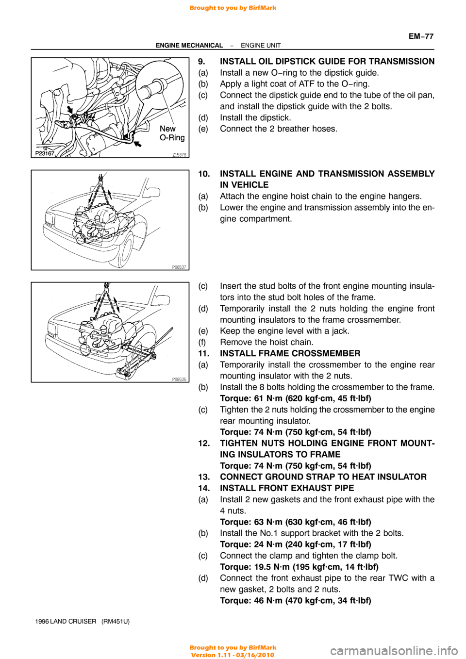
9. INSTALL OIL DIPSTICK GUIDE FOR TRANSMISSION
(a) Install a new O−ring to the dipstick guide.
(b) Apply a light coat of ATF to the O −ring.
(c) Connect the dipstick guide end to the tube of the oil pan, and install the dipstick guide with the 2 bolts.
(d) Install the dipstick.
(e) Connect the 2 breather hoses.
10. INSTALL ENGINE AND TRANSMISSION ASSEMBLY IN VEHICLE
(a) Attach the engine hoist chain to the engine hangers.
(b) Lower the engine and transmission assembly into the en-
gine compartment.
(c) Insert the stud bolts of the front engine mounting insula- tors into the stud bolt holes of the frame.
(d) Temporarily install the 2 nuts holding the engine front mounting insulators to the frame crossmember.
(e) Keep the engine level with a jack.
(f) Remove the hoist chain.
11. INSTALL FRAME CROSSMEMBER
(a) Temporarily install the crossmember to the engine rear mounting insulator with the 2 nuts.
(b) Install the 8 bolts holding the crossmember to the frame. Torque: 61 N·m (620 kgf·cm, 45 ft·lbf)
(c) Tighten the 2 nuts holding the crossmember to the engine
rear mounting insulator.
Torque: 74 N·m (750 kgf·cm, 54 ft·lbf)
12. TIGHTEN NUTS HOLDING ENGINE FRONT MOUNT- ING INSULATORS TO FRAME
Torque: 74 N·m (750 kgf·cm, 54 ft·lbf)
13. CONNECT GROUND STRAP TO HEAT INSULATOR
14. INSTALL FRONT EXHAUST PIPE
(a) Install 2 new gaskets and the front exhaust pipe with the
4 nuts.
Torque: 63 N·m (630 kgf·cm, 46 ft·lbf)
(b) Install the No.1 support bracket with the 2 bolts.
Torque: 24 N·m (240 kgf·cm, 17 ft·lbf)
(c) Connect the clamp and tighten the clamp bolt. Torque: 19.5 N·m (195 kgf·cm, 14 ft·lbf)
(d) Connect the front exhaust pipe to the rear TWC with a
new gasket, 2 bolts and 2 nuts.
Torque: 46 N·m (470 kgf·cm, 34 ft·lbf)
Brought to you by BirfMark
Brought to you by BirfMark
Version 1.11 - 03/16/2010
Page 866 of 1399

−
ENGINE MECHANICAL ENGINE UNIT
EM−81
1996 LAND CRUISER (RM451U)
26. CONNECT EVAP HOSE
27. CONNECT BRAKE BOOSTER VACUUM HOSE
28. CONNECT HEATER VALVE AND ENGINE WIRE TO
COWL PANEL
(a) Connect the heater valve with the 2 bolts.
(b) Connect the engine wire and ground strap with the 2 bolts.
29. CONNECT HEATER HOSES
30. CONNECT ACCELERATOR CABLE TO THROTTLE BODY
31. CONNECT CRUISE CONTROL ACTUATOR CABLE TO
THROTTLE BODY
32. INSTALL AIR CLEANER CASE
33. INSTALL AIR CLEANER HOSE AND CAP
34. CONNECT OIL COOLER HOSE TO OIL COOLER PIPE
35. INSTALL RADIATOR (See page CO−16)
36. INSTALL RADIATOR GRILLE
Install the radiator grille with the 5 screws and clip.
37. INSTALL BATTERY TRAY AND BATTERY
(a) Install the battery tray with the 5 bolts.
(b) Connect the ground strap with the bolt.
(c) Install the battery and hold−down clamp with the nuts.
(d) Connect the battery cables.
38. FILL WITH ENGINE OIL
39. FILL RADIATOR WITH ENGINE COOLANT
40. START ENGINE AND CHECK FOR LEAKS
41. CHECK AUTOMATIC TRANSMISSION FLUID LEVEL
42. CHECK IGNITION TIMING (See page EM−10)
43. INSTALL HOOD
44. PERFORM ROAD TEST
Check for abnormal noise, shock, slippage, correct shift points
and smooth operation.
45. RECHECK ENGINE COOLANT AND ENGINE OIL LEV-
ELS
Brought to you by BirfMark
Brought to you by BirfMark
Version 1.11 - 03/16/2010