Page 1008 of 1399
PP3KK−01
−
PREPARATION BODY ELECTRICAL
PP−67
1996 LAND CRUISER (RM451U)
SSM (Special Service Materials)
08833−00070Adhesive 1324,
THREE BOND 1324 or equivalentPower seat housing set nut
Power seat slide and vertical motor set
screw
08833−00080Adhesive 1344
THREE BOND 1344
LOCTITE 242 or equivalentLow oil pressure warning switch
Engine coolant temperature sender
gauge
08888−88888DuPont Paste No. 4817 or
equivalentRear window defogger
Brought to you by BirfMark
Brought to you by BirfMark
Version 1.11 - 03/16/2010
Page 1111 of 1399
SA1UQ−01
SA−48
−
SUSPENSION AND AXLE FRONT DIFFERENTIAL CARRIER
1996 LAND CRUISER (RM451U)
INSTALLATION
Installation is in the reverse order of removal (see page SA−27).
HINT:
�w/ differential lock:
Before installation, check differential lock operation connecting the connector of the actuator to the
connector of the vehicle side.
�w/ differential lock:
Before installation, check that the sleeves on work with switching over the differential lock control
switch.
After checking, lock the front differential.
�After installation, fill the differential with gear oil (See page SA−27).
�w/ differential lock:
After installation, check that the bleeder plug at the point of the bleeder tu\
be (inside of the engine room)
is not damaged or worn.
Brought to you by BirfMark
Brought to you by BirfMark
Version 1.11 - 03/16/2010
Page 1189 of 1399

SF1ED−04
−
SFI SFI SYSTEM
SF−1
629
Author�: Date�:
1996 LAND CRUISER (RM451U)
SFI SYSTEM
PRECAUTION
1. BEFORE WORKING ON FUEL SYSTEM, DISCON-
NECT NEGATIVE (−) TERMINAL CABLE FROM THE
BATTERY.
HINT:
Any diagnostic trouble code retained by the computer will be
erased when the negative ( −) terminal cable is disconnected.
Therefore, if necessary, read the diagnosis before disconnect-
ing the negative ( −) terminal cable from the battery.
2. DO NOT SMOKE OR WORK NEAR AN OPEN FLAME WHEN WORKING ON FUEL SYSTEM.
3. KEEP GASOLINE AWAY FROM RUBBER OR
LEA TH-
ER PARTS
4. MAINTENANCE PRECAUTIONS
(a) In event of engine misfire, these precautions should be taken.
(1) Check proper connection of battery terminals, etc.
(2) Handle high −tension cords carefully.
(3) After repair work, check that the ignition coil termi- nals and all other ignition system lines are recon-
nected securely.
(4) When cleaning the engine compartment, be espe-
cially careful to protect the electrical system from
water.
(b) Precautions when handling the oxygen sensor. (1) Do not allow the oxygen sensor to drop or hit
against an object.
(2) Do not allow the sensor to come in contact with wa- ter.
5. IF VEHICLE IS EQUIPPED WITH MOBILE RA-
DIO
SYSTEM (HAM, CB, ETC.)
If the vehicle is equipped with a mobile communication system,
refer to the precaution in the IN section.
6. AIR INDUCTION SYSTEM
(a) Separation of the engine oil dipstick, oil filler cap, PCV hose, etc. may cause the engine to run out of tune.
(b) Disconnection, looseness or cracks in the parts of the air
induction system between the throttle body and cylinder
head will allow air suction and cause the engine to run out
of tune.
7. ELECTRONIC CONTROL SYSTEM
(a) Before removing SFI wiring connectors, terminals, etc., first disconnect the power by either turning the ignition
switch OFF or disconnecting the negative ( −) terminal
cable from the battery.
Brought to you by BirfMark
Brought to you by BirfMark
Version 1.11 - 03/16/2010
Page 1191 of 1399

FI1654
Fulcrum Length
30 cm
SST
−
SFI SFI SYSTEM
SF−3
631
Author�: Date�:
1996 LAND CRUISER (RM451U)
8. FUEL SYSTEM
(a) When disconnecting the high fuel pressure line, a large
amount of gasoline will spill out, so observe the following
procedures:
(1) Disconnect the fuel pump connector.
(2) Start the engine. After the engine has stopped onits own, turn off the ignition switch.
(3) Put a container under the connection.
(4) Slowly loosen the connection.
(5) Disconnect the connection.
(6) Plug the connection with 2 rubber plugs.
(7) Reconnect the fuel pump connector.
(b) When connecting the union bolt on the high pressure pipe
union, observe the following procedures:
(1) Always use a new gasket.
(2) Tighten the union bolt by hand.
(3) Tighten the union bolt to the specified torque.
Torque: 29 N·m (300 kgf·cm, 21 ft·lbf)
(c) When connecting the flare nut on the high pressure pipe union, observe the following procedures:
(1) Apply a light coat of engine oil to the flare and tight-
en the flare nut by hand.
(2) Using SST, tighten the flare nut to the specified torque.
SST 09631−22020
NOTICE:
Do not rotate the fuel pipe, when tightening the flare nut.
Torque: 30 N·m (310 kgf·cm, 22 ft·lbf)
HINT:
Use a torque wrench with a fulcrum length of 30 cm (11.81 in.).
Brought to you by BirfMark
Brought to you by BirfMark
Version 1.11 - 03/16/2010
Page 1192 of 1399

P09286
New O−ring
Grommet Injector
Delivery Pipe WRONG
CORRECT
P09401
Fuel Return Hose
SF−4
−
SFI SFI SYSTEM
632
Author�: Date�:
1996 LAND CRUISER (RM451U)
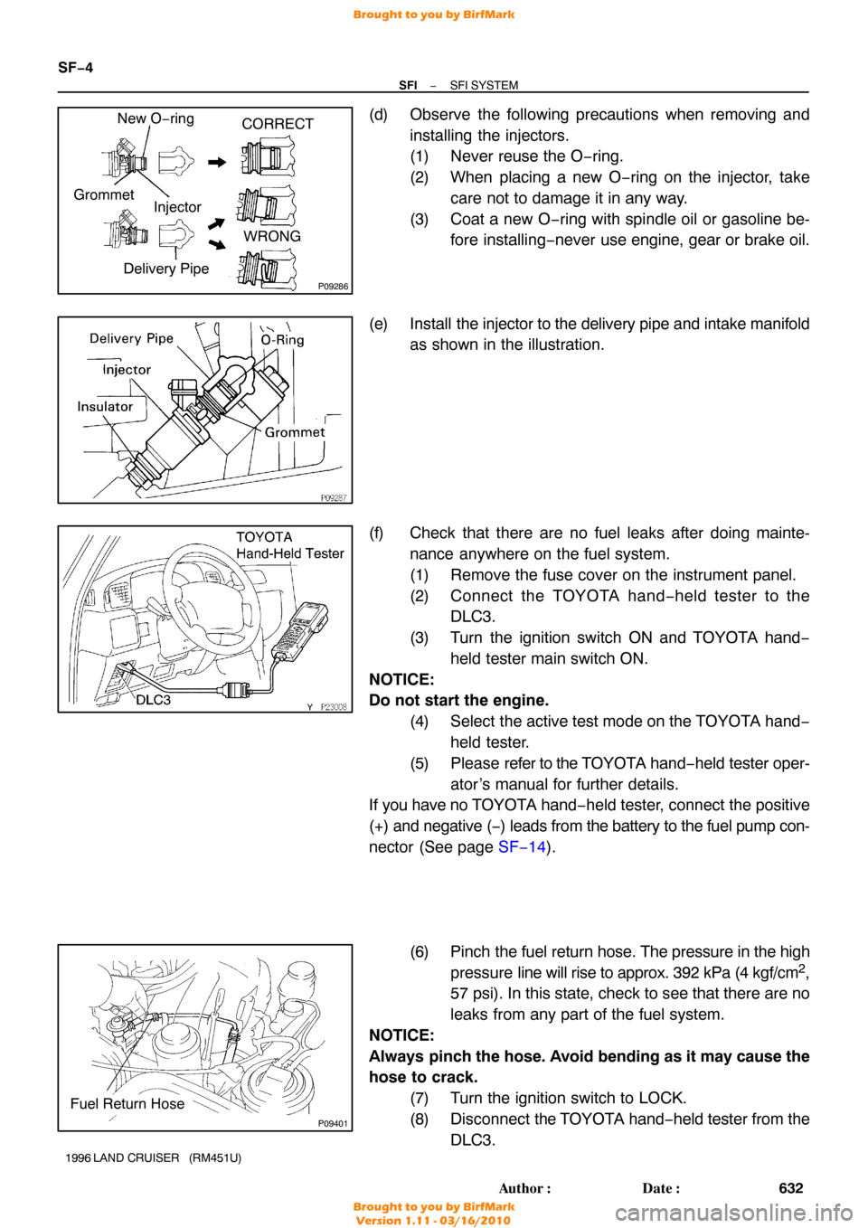
(d) Observe the following precautions when removing and
installing the injectors.
(1) Never reuse the O −ring.
(2) When placing a new O −ring on the injector, take
care not to damage it in any way.
(3) Coat a new O −ring with spindle oil or gasoline be-
fore installing −never use engine, gear or brake oil.
(e) Install the injector to the delivery pipe and intake manifold
as shown in the illustration.
(f) Check that there are no fuel leaks after doing mainte- nance anywhere on the fuel system.
(1) Remove the fuse cover on the instrument panel.
(2) Connect the TOYOTA hand− held tester to the
DLC3.
(3) Turn the ignition switch ON and TOYOTA hand −
held tester main switch ON.
NOTICE:
Do not start the engine. (4) Select the active test mode on the TOYOTA hand−held tester.
(5) Please refer to the TOYOTA hand −held tester oper-
ator ’s manual for further details.
If you have no T OYOTA hand−held tester, connect the positive
(+) and negative ( −) leads from the battery to the fuel pump con-
nector (See page SF−14 ).
(6) Pinch the fuel return hose. The pressure in the high
pressure line will rise to approx. 392 kPa (4 kgf/cm
2,
57 psi). In this state, check to see that there are no
leaks from any part of the fuel system.
NOTICE:
Always pinch the hose. Avoid bending as it may cause the
hose to crack.
(7) Turn the ignition switch to LOCK.
(8) Disconnect the TOYOTA hand −held tester from the
DLC3.
Brought to you by BirfMark
Brought to you by BirfMark
Version 1.11 - 03/16/2010
Page 1213 of 1399
−
SFI INJECTOR
SF−27
1996 LAND CRUISER (RM451U)
18. DISCONNECT PS RESERVOIR TANK
Remove the 3 bolts and disconnect the reservoir tank.
19. REMOVE ENGINE OIL DIPSTICK
20. DISCONNECT GROUND STRAP
21. REMOVE INTAKE MANIFOLD STAY
Remove the 2 bolts and intake manifold stay.
22. DISCONNECT VACUUM HOSES FROM TVV
23. DISCONNECT NO.1 WATER BYPASS HOSE FROM
CYLINDER HEAD
24. REMOVE AIR INTAKE CHAMBER
Remove the 6 bolts, 2 nuts, air intake chamber and 2 gaskets.
25. REMOVE FUEL RETURN PIPE
(a) Disconnect the fuel hose from the fuel pressure regulator.
(b) Remove the 2 bolts and fuel return pipe.
Brought to you by BirfMark
Brought to you by BirfMark
Version 1.11 - 03/16/2010
Page 1220 of 1399

SF−34
−
SFI INJECTOR
1996 LAND CRUISER (RM451U)
7. INSTALL INTAKE MANIFOLD STAY
Install the intake manifold stay with the 2 bolts.
Torque: 36 N·m (360 kgf·cm, 26 ft·lbf)
8. CONNECT GROUND STRAP
9. INSTALL ENGINE OIL DIPSTICK
10. CONNECT PS RESERVOIR TANK
Connect the reservoir tank with the 3 bolts. Torque: 18 N·m (185 kgf·cm, 13 ft·lbf)
11. CONNECT EGR GAS TEMP. SENSOR CONNECTOR
12. CONNECT CONNECTOR FOR EMISSION CONTROL VALVE SET ASSEMBLY
13. CONNECT IDLE AIR CONTROL VALVE CONNECTOR
14. CONNECT THROTTLE POSITION SENSOR CONNEC- TOR
15. CONNECT BRAKE BOOSTER HOSE
16. CONNECT EVAP HOSE
17. CONNECT NO.2 WATER BYPASS HOSE
18. CONNECT VACUUM SENSING HOSE
19. CONNECT NO.1 PCV HOSE
20. INSTALL BOLT HOLDING HEATER INLET PIPE AND AIR INTAKE CHAMBER
Torque: 20 N·m (200 kgf·cm, 14 ft·lbf)
21. INSTALL EGR VALVE AND VACUUM MODULATOR (See page EC−10 )
22. CONNECT THROTTLE CABLE
23. CONNECT ACCELERATOR CABLE
24. CONNECT CRUISE CONTROL ACTUATOR CABLE
25. CONNECT AIR CLEANER HOSE
26. CONNECT NO.2 PCV HOSE
Brought to you by BirfMark
Brought to you by BirfMark
Version 1.11 - 03/16/2010
Page 1257 of 1399

SR166−01
R07281
Normal Abnormal
SR−4
−
STEERING POWER STEERING FLUID
1996 LAND CRUISER (RM451U)
INSPECTION
1. CHECK FLUID LEVEL
(a) Keep the vehicle level.
(b) With the engine stopped, check the fluid level in the oil reservoir.
If necessary, add fluid.
Fluid: ATF DEXRON® II or III
HINT:
Check that the fluid level is within the HOT LEVEL range on the
reservoir cap dipstick. If the fluid is cold, check that it is within
the COLD LEVEL range.
(c) Start the engine and run it at idle.
(d) Turn the steering wheel from lock to lock several times to
boost fluid temperature.
Fluid temperature: 80° C (176°F)
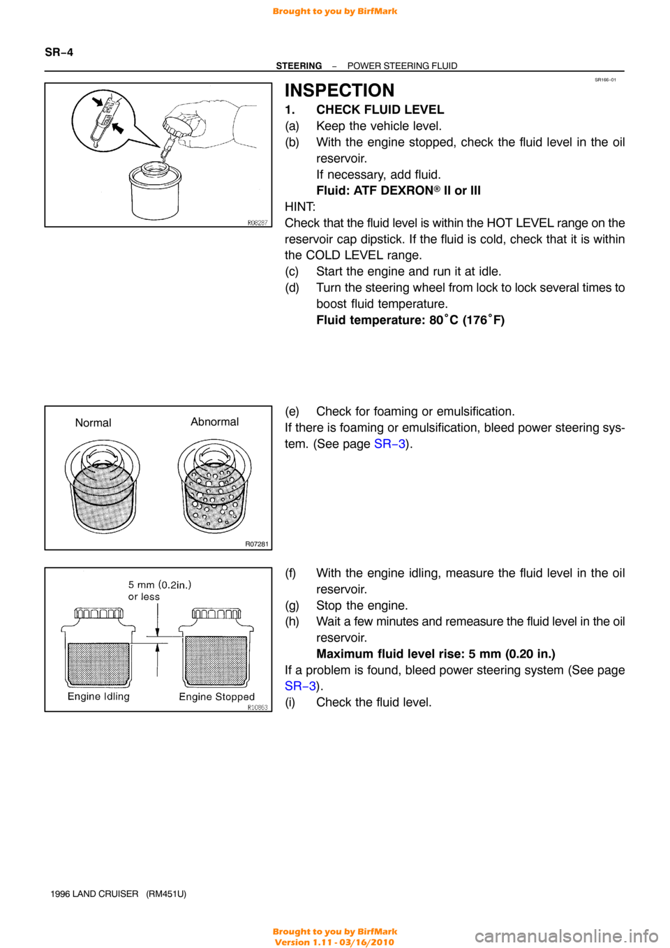
(e) Check for foaming or emulsification.
If there is foaming or emulsification, bleed power steering sys-
tem. (See page SR−3 ).
(f) With the engine idling, measure the fluid level in the oil reservoir.
(g) Stop the engine.
(h) Wait a few minutes and remeasure the fluid level in the oil reservoir.
Maximum fluid level rise: 5 mm (0.20 in.)
If a problem is found, bleed power steering system (See page
SR−3 ).
(i) Check the fluid level.
Brought to you by BirfMark
Brought to you by BirfMark
Version 1.11 - 03/16/2010