Page 562 of 2890
G2M0345
3. Fuel Tank
A: REMOVAL
1) Release fuel pressure.
2) Drain fuel from fuel tank.
G2M0382
3) Remove rear exhaust pipe.
(1) Lift-up the vehicle.
(2) Separate rear exhaust pipe from center exhaust
pipe.
(3) Separate rear exhaust pipe from muffler.
(4) Remove bracket from rubber cushion, and remove
exhaust pipe.
NOTE:
To facilitate the removal of parts, apply a coat of SUBARU
CRC5-56 (Part No. 004301003)
G2M0384
4) Remove muffler assembly.
NOTE:
To facilitate the removal of parts, apply a coat of SUBARU
CRC5-56 (Part No. 004301003)
G3M0059
5) Remove rear differential assembly. (AWD model)
(1) Remove rear axle shafts from rear differential
assembly.
(2) Remove rear differential front cover.
(3) Remove propeller shaft.
(4) Remove lower differential bracket.
(5) Set transmission jack under rear differential.
(6) Remove bolts which install rear differential onto
rear crossmember.
13
2-8SERVICE PROCEDURE
3. Fuel Tank
Page 565 of 2890
G3M0059
6) Install rear differential assembly.
G2M0384
7) Install muffler assembly.
G2M0382
8) Install heat sealed cover.
9) Install rear exhaust pipe.
G2M0340
10) Lower the vehicle, and connect connector to fuel
pump.
11) Install access hole lid.
G2M0345
4. Fuel Filler Pipe
A: REMOVAL
1) Release fuel pressure.
2) Drain fuel from fuel tank.
16
2-8SERVICE PROCEDURE
3. Fuel Tank - 4. Fuel Filler Pipe
Page 567 of 2890
G2M0358
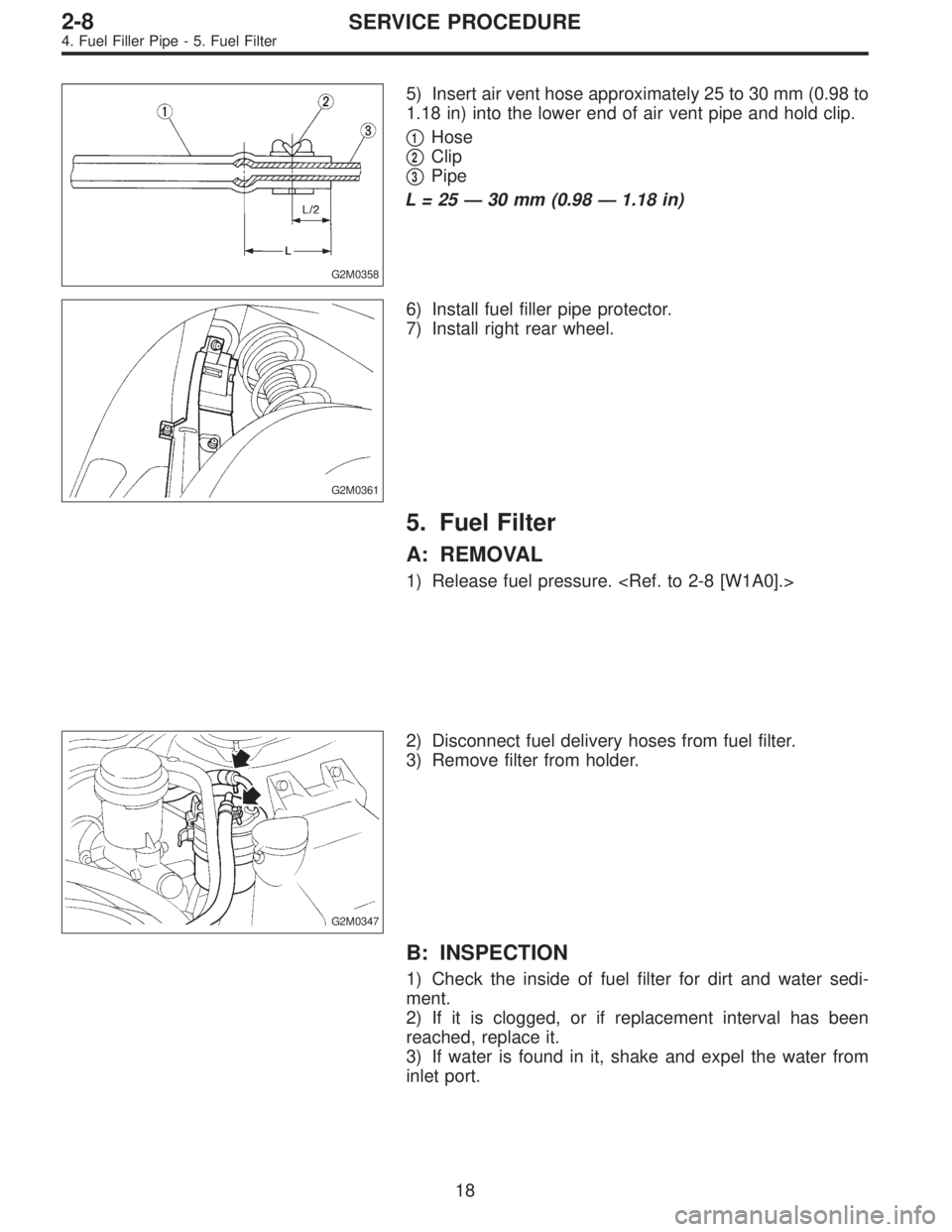
5) Insert air vent hose approximately 25 to 30 mm (0.98 to
1.18 in) into the lower end of air vent pipe and hold clip.
�
1Hose
�
2Clip
�
3Pipe
L=25—30 mm (0.98—1.18 in)
G2M0361
6) Install fuel filler pipe protector.
7) Install right rear wheel.
5. Fuel Filter
A: REMOVAL
1) Release fuel pressure.
G2M0347
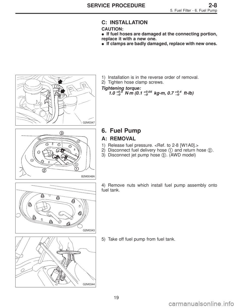
2) Disconnect fuel delivery hoses from fuel filter.
3) Remove filter from holder.
B: INSPECTION
1) Check the inside of fuel filter for dirt and water sedi-
ment.
2) If it is clogged, or if replacement interval has been
reached, replace it.
3) If water is found in it, shake and expel the water from
inlet port.
18
2-8SERVICE PROCEDURE
4. Fuel Filler Pipe - 5. Fuel Filter
Page 568 of 2890
C: INSTALLATION
CAUTION:
�If fuel hoses are damaged at the connecting portion,
replace it with a new one.
�If clamps are badly damaged, replace with new ones.
G2M0347
1) Installation is in the reverse order of removal.
2) Tighten hose clamp screws.
Tightening torque:
1.0
+0.5
�0N⋅m (0.1+0.05
�0kg-m, 0.7+0.4
�0ft-lb)
B2M0048A
6. Fuel Pump
A: REMOVAL
1) Release fuel pressure.
2) Disconnect fuel delivery hose�
1and return hose�2.
3) Disconnect jet pump hose�
3. (AWD model)
G2M0343
4) Remove nuts which install fuel pump assembly onto
fuel tank.
G2M0344
5) Take off fuel pump from fuel tank.
19
2-8SERVICE PROCEDURE
5. Fuel Filter - 6. Fuel Pump
Page 569 of 2890

G2M0366
B: INSPECTION
Connect lead harness to connector terminal of fuel pump,
and apply battery power supply to check whether the pump
operate.
WARNING:
�Wipe off the fuel completely.
�Keep battery as far apart from fuel pump as pos-
sible.
�Be sure to turn the battery supply ON and OFF on
the battery side.
�Do not run fuel pump for a long time under non-load
condition.
G2M0346
C: INSTALLATION
Installation is in the reverse order of removal. Do the fol-
lowing:
(1) Always use new gaskets.
(2) Ensure sealing portion is free from fuel or foreign
particles before installation.
(3) Tighten nuts in numerical sequence shown in Fig-
ure to specified torque.
Tightening torque:
4.4±1.5 N⋅m (0.45±0.15 kg-m, 3.3±1.1 ft-lb)
B2M0048A
7. Fuel Meter Unit
A: REMOVAL
NOTE:
Fuel meter unit is built in fuel pump assembly.
1) Release fuel pressure.
2) Disconnect fuel delivery hose�
1and return hose�2.
3) Disconnect jet pump hose�
3. (AWD model)
20
2-8SERVICE PROCEDURE
6. Fuel Pump - 7. Fuel Meter Unit
Page 571 of 2890
8. Fuel Delivery, Return and
Evaporation Lines
A: REMOVAL
1) Release fuel pressure.
2) Remove inner trim, insulator and rear seat.
3) Remove fuel delivery pipes and hoses, fuel return pipes
and hoses, and evaporation pipes and hoses.
B2M0971A
B2M0972A
22
2-8SERVICE PROCEDURE
8. Fuel Delivery, Return and Evaporation Lines
Page 576 of 2890
 Fuel pump will not operate.
�Defective terminal contact.Inspect connections, especially groun")
1. Fuel System
Trouble and possible cause Corrective action
1. Insufficient fuel supply to the injector
1) Fuel pump will not operate.
�Defective terminal contact.Inspect connections, especially ground, and tighten
securely.
�Trouble in electromagnetic or electronic circuit parts. Replace fuel pump.
2) Lowering of fuel pump function. Replace fuel pump.
3) Clogged dust or water in the fuel filter. Replace fuel filter, clean or replace fuel tank.
4) Clogged or bent fuel pipe or hose. Clean, correct or replace fuel pipe or hose.
5) Air is mixed in the fuel system. Inspect or retighten each connection part.
6) Clogged or bent breather tube or pipe. Clean, correct or replace air breather tube or pipe.
7) Damaged diaphragm of pressure regulator. Replace.
2. Leakage or blow out fuel
1) Loosened joints of the fuel pipe. Retightening.
2) Cracked fuel pipe, hose and fuel tank. Replace.
3) Defective welding part on the fuel tank. Replace.
4) Defective drain packing of the fuel tank. Replace.
5) Clogged or bent air breather tube or air vent tube. Clean, correct or replace air breather tube or air vent tube.
3. Gasoline smell inside of compartment
1)Loose joints at air breather tube, air vent tube and fuel filler
pipe.Retightening.
2) Defective packing air tightness on the fuel saucer. Correct or replace packing.
3) Cracked fuel separator. Replace separator.
4. Defective fuel meter indicator
1) Defective operation of fuel meter unit. Replace.
2) Defective operation of fuel meter. Replace.
5. Noise
1) Large operation noise or vibration of fuel pump. Replace.
NOTE:
When the vehicle is left unattended for an extended period of time, water may accumulate in the fuel
tank.
�To prevent water condensation:
1) Top off the fuel tank or drain the fuel completely.
2) Drain water condensation from the fuel filter.
�Refilling the fuel tank:
Refill the fuel tank while there is still some fuel left in the tank.
�Protecting the fuel system against freezing and water condensation:
1) Cold areas
In snow-covered areas, mountainous areas, skiing areas, etc. where ambient temperatures drop
below 0°C (32°F) throughout the winter season, use an anti-freeze solution in the cooling system.
Refueling will also complement the effect of anti-freeze solution each time the fuel level drops to about
one-half. After the winter season, drain water which may have accumulated in the fuel filter and fuel
tank in the manner same as that described under affected areas as below.
2) Affected areas
When water condensation is notched in the fuel filter, drain water from both the fuel filter and fuel tank
or use a water removing agent (or anti-freeze solution) in the fuel tank.
�Observe the instructions, notes, etc., indicated on the label affixed to the anti-freeze solution (water
removing agent) container before use.
27
2-8DIAGNOSTICS
1. Fuel System
Page 602 of 2890
B2M0323
5) Remove radiator fan motor assembly.
6) Remove fan motor from shroud.
B: INSTALLATION
Installation is in the reverse order of removal procedures.
Do the following:
1) Before installing radiator fan motor, apply a coat of seal-
ant to threads and tighten nuts.
2) Make sure radiator fan does not come into contact with
shroud when installed.
3) After installation, make sure there is no unusual noise
or vibration when fan is rotated.
G6M0095
7. Engine Coolant Pipe
A: REMOVAL
1) Release fuel pressure.
2) Disconnect ground cable from the battery.
B2M0015A
3) Drain engine coolant completely.
B2M0160
4) Remove intake manifold.
17
2-5SERVICE PROCEDURE
6. Radiator Fan and Fan Motor - 7. Engine Coolant Pipe
![SUBARU LEGACY 1996 Service Repair Manual G2M0345
3. Fuel Tank
A: REMOVAL
1) Release fuel pressure. <Ref. to 2-8 [W1A0].>
2) Drain fuel from fuel tank. <Ref. to 2-8 [W1B0].>
G2M0382
3) Remove rear exhaust pipe.
(1) Lift-up the vehicle.
(2) Se](/manual-img/17/57433/w960_57433-561.png "SUBARU LEGACY 1996 Service Repair Manual G2M0345
3. Fuel Tank
A: REMOVAL
1) Release fuel pressure. <Ref. to 2-8 [W1A0].>
2) Drain fuel from fuel tank. <Ref. to 2-8 [W1B0].>
G2M0382
3) Remove rear exhaust pipe.
(1) Lift-up the vehicle.
(2) Se")
![SUBARU LEGACY 1996 Service Repair Manual G3M0059
6) Install rear differential assembly. <Ref. to 3-4 [W2F0].>
G2M0384
7) Install muffler assembly.
G2M0382
8) Install heat sealed cover.
9) Install rear exhaust pipe.
G2M0340
10) Lower the vehi](/manual-img/17/57433/w960_57433-564.png "SUBARU LEGACY 1996 Service Repair Manual G3M0059
6) Install rear differential assembly. <Ref. to 3-4 [W2F0].>
G2M0384
7) Install muffler assembly.
G2M0382
8) Install heat sealed cover.
9) Install rear exhaust pipe.
G2M0340
10) Lower the vehi")
![SUBARU LEGACY 1996 Service Repair Manual 8. Fuel Delivery, Return and
Evaporation Lines
A: REMOVAL
1) Release fuel pressure. <Ref. to 2-8 [W1A0].>
2) Remove inner trim, insulator and rear seat.
3) Remove fuel delivery pipes and hoses, fuel r](/manual-img/17/57433/w960_57433-570.png "SUBARU LEGACY 1996 Service Repair Manual 8. Fuel Delivery, Return and
Evaporation Lines
A: REMOVAL
1) Release fuel pressure. <Ref. to 2-8 [W1A0].>
2) Remove inner trim, insulator and rear seat.
3) Remove fuel delivery pipes and hoses, fuel r")
 Remove radiator fan motor assembly.
6) Remove fan motor from shroud.
B: INSTALLATION
Installation is in the reverse order of removal procedures.
Do the following:
1) Before installing radia")