Page 270 of 2890

6-3
IDso1a1
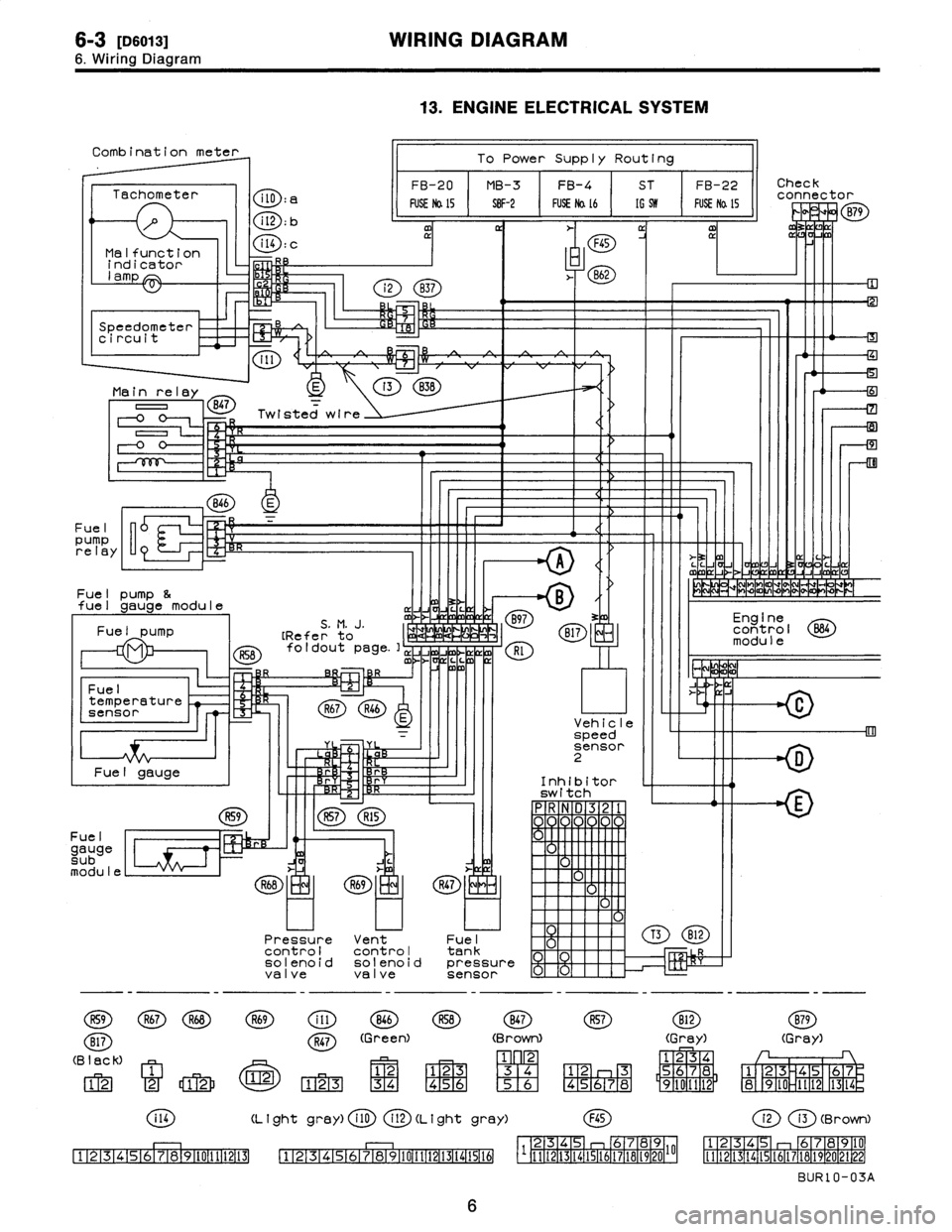
WIRING
DIAGRAM
6
.
Wiring
Diagram
R57R15
Combination
meter
To
Power
Supply
Routing
FB-20
MB-3FB-4
ST
FB-22Check
Tachometer
connector
FUSE
Na
15
S8F-2
FUSE
Na
16
[G
519
FUSE
Na
l5
P
v
1-0
B79
CD
:
bm
rI
a
m
~
~
F45
Malfunction
Q
D
:
C
indicator
,
.
862
lamp
7
Speedometer
B
i
circuit
I11
*c~
)
Main
relay
E
o
B47
=
Twisted
wire
=2
R
0
F-0
0-
<
71
846
E
Fuel
pump
relay
"
>-
3z
M
~`
LL
J
C
A
V
mJ
(7
Fue
I
pump
&
~
MM~mVPPP
-+
fuel
gauge
module
~
Jv
Fue
I
S
.
M
.
J
.
mJ
B97
3
Engine
pump
[Refer'
to
a
1,
B17
control
B84
module
foldout
page
.],
JJ
Rl
~/
m
L
C
O
R
Fuel
ix
J
temperature
R67R46
sensor
u
Vehicle
=
speed
'
rr
sensor
D
Fuel
gauge
~
r
Inhibitor
switch
n
R59
Fue
I
gauge
C~
sub
module
R59
R67R68
B17
(B
lack)
12
2
12
C
i14
111213141516171819110111112113
((
9
)
5
1
F1F1
Pressure
Vent
controlcontrol
solenoid
solenoi
valvevalve
R69
OD
846
R47
(Green)
U
:Z~)
123
~
34
13
.
ENGINE
ELECTRICAL
SYSTEM
R47
F-1
Fuel
tank
d
pressure
sensor
(Brown)
M
F1F2-1
'
2
3
[3141
456
1516
(L
I
ght
gray)
i
10
(
2D
(L
i
ght
gray)
12345678910111213(41516
B12
R57B12
(Gray)
1234
12
3
5678
45678
9101112
F45
B79
(Gray)
1
23
45
67
89
IO
1t
12
1314
(2i3
(Brown)
23456789
12345
678910
1111213141516171819201
[t
1
1
12
1
13
1
14
1
15
1
16
1
17
1
18
1
19
1
20
21
1
99
1
BUR10-03A
6
Page 275 of 2890
8
.
Electrical
Wiring
Harness
and
Ground
Point
Connector
Connecting
to
No
.
Pole
Color
Area
No
.
Name
R156
B-2
B97
Bulkhead
wiring
harness
(S
.M
.J
.)
R4
1
Black
B-2
Parking
brake
switch
R5
2B-2
Select
lever
illumination
light
R6
2
Black
B-2
Shift
lock
solenoid
R7
2B-2P
position
switch
RS
2B-2
Seat
belt
switch
R9
1
Brown
B-3Front
door
switch
LH
R11
8
B-4D21
Rear
doorcord
LH
R12
1
Brown
B-2
Front
door
switch
RH
R14
8
B-2
D27
Rear
door
cord
RH
R15
8B-3
R57
Fueltank
cord
R16
1
Brown
A-3
Rear
door
switch
RH
R30
2
Black
B-2
Diode
(Rear
gale
latch
switch)
R46
2
B3
R67
Fuel
lankcord
R50
2
Green
B-2
890
Bulkhead
wiring
harness
R52
2
A-3
Room
light
R57
S
B-3
R15
Rear
wiring
harness
R58
6
A-3
Fuel
gaugemodule
&
fuel
pump
R59
2
B-4
Fuel
gauge
submodule
R67
2
B-3
R46
Rear
wiring
harness
R68
2B-3
Pressure
control
solenoid
valve
R69
I
2
A-3
Vent
control
solenoid
valve
non-coiorea
A
B
C
n
6
.
REAR
WIRING
HARNESS
AND
GROUND
POINT
1
I
2
I
3
I
4
2
~S
4
[D806]
B6M0695A
A
B
C
u
Page 276 of 2890
8
.
Electrical
Wiring
Harness
and
Ground
Point
Connector
Connecting
to
No
.
Pole
Color
Area
No
.
Name
R156
B-2
B97
Bulkhead
wiring
harness
(S
.M
.J
.)
R4
1
Black
B-2
Parking
brake
switch
R5
2B-2
Select
lever
illumination
light
R6
2
Black
B-2
Shift
lock
solenoid
R7
2B-2P
position
switch
RS
2B-2
Seat
belt
switch
R9
1
Brown
B-3Front
door
switch
LH
R11
8
B-4D21
Rear
doorcord
LH
R12
1
Brown
B-2
Front
door
switch
RH
R14
8
B-2
D27
Rear
door
cord
RH
R15
8B-3
R57
Fueltank
cord
R16
1
Brown
A-3
Rear
door
switch
RH
R30
2
Black
B-2
Diode
(Rear
gale
latch
switch)
R46
2
B3
R67
Fuel
lankcord
R50
2
Green
B-2
890
Bulkhead
wiring
harness
R52
2
A-3
Room
light
R57
S
B-3
R15
Rear
wiring
harness
R58
6
A-3
Fuel
gaugemodule
&
fuel
pump
R59
2
B-4
Fuel
gauge
submodule
R67
2
B-3
R46
Rear
wiring
harness
R68
2B-3
Pressure
control
solenoid
valve
R69
I
2
A-3
Vent
control
solenoid
valve
non-coiorea
A
B
C
n
6
.
REAR
WIRING
HARNESS
AND
GROUND
POINT
1
I
2
I
3
I
4
2
~S
4
[D806]
B6M0695A
A
B
C
u
Page 277 of 2890
Connector
Connecting
to
No
.
Pole
Color
Area
No
.
Name
R22
1
Brown
C-1
Rear
door
switch
LH
R23
6
G2
Power
antenna
R25
2
Black
C-3
Rear
defogger
condenser
R26
4
Black
D-4
Rear
combination
light
RH
R28
4
Black
C-2
Rear
combination
light
LH
R36
5
Black
C-3
Rear
wiper
relay
R37
2
C-3
D33
R38
4
G3
D34
Rear
gatecord
R39
8
C-4
D35
R47
3
I
D-3
I
Fuel
tank
pressure
sensor
Connector
Connecting
to
No
.
Pole
Color
Area
No
.
Name
D33
2
C-3
R37
D34
4C-3
R38
Rear
wiring
harness
D35
8
C-4
R39
D37
1
Black
B-3L
li
D38
1
B-3
uggage
room
ght
D39
2B-3
High-mounted
stop
light
D40
1
Black
B-4
Rear
defogger
(Power)
D42
4B-4
Rear
finisher
light
RH
D43
48-3
Rear
wiper
motor
D44
2B-4
License
plate
light
RH
D45
2A-3
License
plate
light
LH
D46
2
Black
A-4
Rear
gate
latch
switch
D47
4
A-4
Rear
gate
lock
actuator
D48
1
Black
B-3
Rear
defogger
(Ground)
D49
I
4A-3
Rear
finisher
light
LH
''
Non-colored
9
.
REAR
END
WIRING
HARNESS
AND
GROUND
POINT
1
243
B
C
C
D
B6M069
1
2
3_
I
4
13
11`~~Il'//
Page 278 of 2890
Connector
Connecting
to
No
.
Pole
Color
Area
No
.
Name
R22
1
Brown
C-1
Rear
door
switch
LH
R23
6
G2
Power
antenna
R25
2
Black
C-3
Rear
defogger
condenser
R26
4
Black
D-4
Rear
combination
light
RH
R28
4
Black
C-2
Rear
combination
light
LH
R36
5
Black
C-3
Rear
wiper
relay
R37
2
C-3
D33
R38
4
G3
D34
Rear
gatecord
R39
8
C-4
D35
R47
3
I
D-3
I
Fuel
tank
pressure
sensor
Connector
Connecting
to
No
.
Pole
Color
Area
No
.
Name
D33
2
C-3
R37
D34
4C-3
R38
Rear
wiring
harness
D35
8
C-4
R39
D37
1
Black
B-3L
li
D38
1
B-3
uggage
room
ght
D39
2B-3
High-mounted
stop
light
D40
1
Black
B-4
Rear
defogger
(Power)
D42
4B-4
Rear
finisher
light
RH
D43
48-3
Rear
wiper
motor
D44
2B-4
License
plate
light
RH
D45
2A-3
License
plate
light
LH
D46
2
Black
A-4
Rear
gate
latch
switch
D47
4
A-4
Rear
gate
lock
actuator
D48
1
Black
B-3
Rear
defogger
(Ground)
D49
I
4A-3
Rear
finisher
light
LH
''
Non-colored
9
.
REAR
END
WIRING
HARNESS
AND
GROUND
POINT
1
243
B
C
C
D
B6M069
1
2
3_
I
4
13
11`~~Il'//
Page 290 of 2890
B2M0425A
7. EGR Solenoid Valve
A: REMOVAL AND INSTALLATION
1) Remove bolt which installs EGR solenoid valve onto
intake manifold.
2) Disconnect hoses and connector from EGR solenoid
valve.
NOTE:
This figure shows the rear side of intake manifold.
3) Installation is in the reverse order of removal.
Tightening torque:
19±5 N⋅m (1.9±0.5 kg-m, 13.7±3.6 ft-lb)
G6M0095
8. Fuel Temperature Sensor (2200 cc
AWD Model)
A: REMOVAL
1) Disconnect battery ground cable.
B2M0954A
2) Release fuel pressure.
3) Disconnect fuel delivery hose�
1, return hose�2and jet
pump hose�
3.
B2M0955
4) Remove nuts which install fuel pump assembly onto
fuel tank.
9
2-1SERVICE PROCEDURE
7. EGR Solenoid Valve - 8. Fuel Temperature Sensor (2200 cc AWD Model)
Page 291 of 2890
B2M0425A
7. EGR Solenoid Valve
A: REMOVAL AND INSTALLATION
1) Remove bolt which installs EGR solenoid valve onto
intake manifold.
2) Disconnect hoses and connector from EGR solenoid
valve.
NOTE:
This figure shows the rear side of intake manifold.
3) Installation is in the reverse order of removal.
Tightening torque:
19±5 N⋅m (1.9±0.5 kg-m, 13.7±3.6 ft-lb)
G6M0095
8. Fuel Temperature Sensor (2200 cc
AWD Model)
A: REMOVAL
1) Disconnect battery ground cable.
B2M0954A
2) Release fuel pressure.
3) Disconnect fuel delivery hose�
1, return hose�2and jet
pump hose�
3.
B2M0955
4) Remove nuts which install fuel pump assembly onto
fuel tank.
9
2-1SERVICE PROCEDURE
7. EGR Solenoid Valve - 8. Fuel Temperature Sensor (2200 cc AWD Model)
Page 293 of 2890

B2M0955A
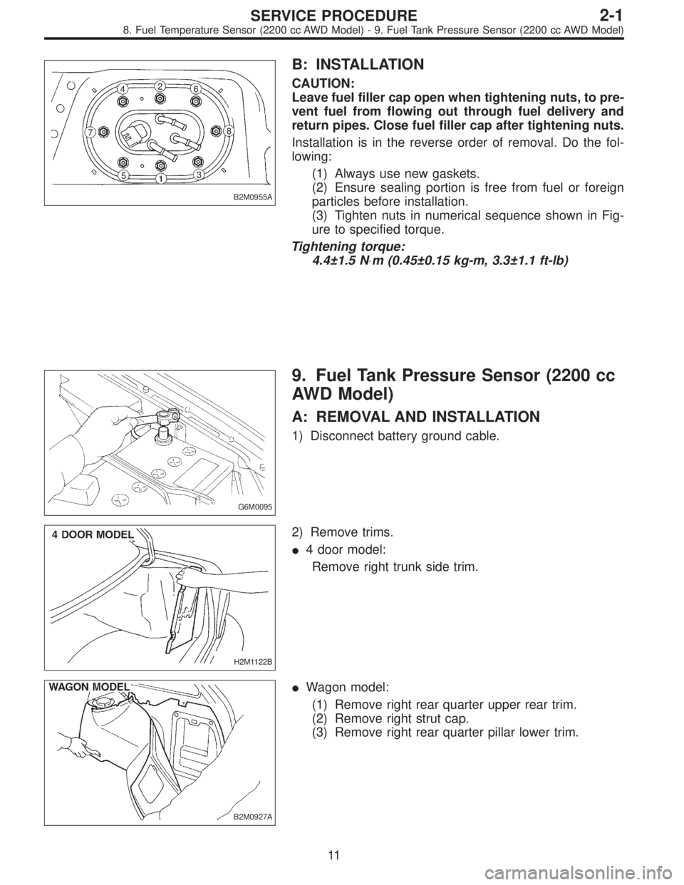
B: INSTALLATION
CAUTION:
Leave fuel filler cap open when tightening nuts, to pre-
vent fuel from flowing out through fuel delivery and
return pipes. Close fuel filler cap after tightening nuts.
Installation is in the reverse order of removal. Do the fol-
lowing:
(1) Always use new gaskets.
(2) Ensure sealing portion is free from fuel or foreign
particles before installation.
(3) Tighten nuts in numerical sequence shown in Fig-
ure to specified torque.
Tightening torque:
4.4±1.5 N⋅m (0.45±0.15 kg-m, 3.3±1.1 ft-lb)
G6M0095
9. Fuel Tank Pressure Sensor (2200 cc
AWD Model)
A: REMOVAL AND INSTALLATION
1) Disconnect battery ground cable.
H2M1122B
2) Remove trims.
�4 door model:
Remove right trunk side trim.
B2M0927A
�Wagon model:
(1) Remove right rear quarter upper rear trim.
(2) Remove right strut cap.
(3) Remove right rear quarter pillar lower trim.
11
2-1SERVICE PROCEDURE
8. Fuel Temperature Sensor (2200 cc AWD Model) - 9. Fuel Tank Pressure Sensor (2200 cc AWD Model)